Page 334 of 382

Maintenance
18
6
LUBRICANTS AND FLUIDS
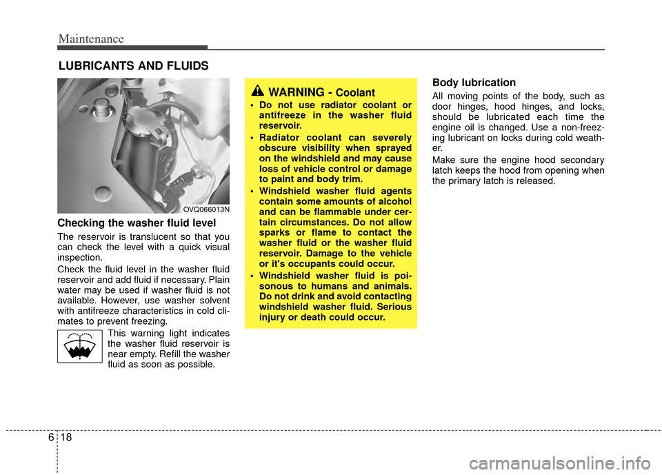
Checking the washer fluid level
The reservoir is translucent so that you
can check the level with a quick visual
inspection.
Check the fluid level in the washer fluid
reservoir and add fluid if necessary. Plain
water may be used if washer fluid is not
available. However, use washer solvent
with antifreeze characteristics in cold cli-
mates to prevent freezing.
This warning light indicatesthe washer fluid reservoir is
near empty. Refill the washer
fluid as soon as possible.
Body lubrication
All moving points of the body, such as
door hinges, hood hinges, and locks,
should be lubricated each time the
engine oil is changed. Use a non-freez-
ing lubricant on locks during cold weath-
er.
Make sure the engine hood secondary
latch keeps the hood from opening when
the primary latch is released.WARNING - Coolant
Do not use radiator coolant or antifreeze in the washer fluid
reservoir.
Radiator coolant can severely obscure visibility when sprayed
on the windshield and may cause
loss of vehicle control or damage
to paint and body trim.
Windshield washer fluid agents contain some amounts of alcohol
and can be flammable under cer-
tain circumstances. Do not allow
sparks or flame to contact the
washer fluid or the washer fluid
reservoir. Damage to the vehicle
or it's occupants could occur.
Windshield washer fluid is poi- sonous to humans and animals.
Do not drink and avoid contacting
windshield washer fluid. Serious
injury or death could occur.
OVQ066013N
Page 335 of 382

619
Maintenance
POWER STEERING
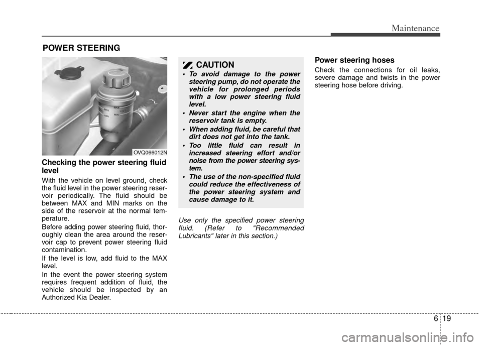
Checking the power steering fluid
level
With the vehicle on level ground, check
the fluid level in the power steering reser-
voir periodically. The fluid should be
between MAX and MIN marks on the
side of the reservoir at the normal tem-
perature.
Before adding power steering fluid, thor-
oughly clean the area around the reser-
voir cap to prevent power steering fluid
contamination.
If the level is low, add fluid to the MAX
level.
In the event the power steering system
requires frequent addition of fluid, the
vehicle should be inspected by an
Authorized Kia Dealer.
Use only the specified power steeringfluid. (Refer to "RecommendedLubricants" later in this section.)
Power steering hoses
Check the connections for oil leaks,
severe damage and twists in the power
steering hose before driving.CAUTION
To avoid damage to the power steering pump, do not operate thevehicle for prolonged periods with a low power steering fluidlevel.
Never start the engine when the reservoir tank is empty.
When adding fluid, be careful that dirt does not get into the tank.
Too little fluid can result in increased steering effort and/ornoise from the power steering sys-tem.
The use of the non-specified fluid could reduce the effectiveness ofthe power steering system andcause damage to it.
OVQ066012N
Page 339 of 382

623
Maintenance
FUSES
A vehicle’s electrical system is protected
from electrical overload damage by
fuses.This vehicle has three fuse panels, one
located in the driver’s side panel bolster,
another in the cargo area, the other in
the engine compartment near the bat-
tery.
If any of your vehicle’s lights, acces-
sories, or controls do not work, check the
appropriate circuit fuse. If a fuse has
blown, the element inside the fuse will be
melted.
If the electrical system does not work,
first check the driver’s side fuse panel.
Before replacing a blown fuse, discon-
nect the negative battery cable.
Always replace a blown fuse with one of
the same rating.
If the replacement fuse blows, this indi-
cates an electrical problem. Avoid using
the system involved and immediately
consult an Authorized Kia Dealer.
Three kinds of fuses are used: blade type
for lower amperage rating and cartridgetype, fusible link for higher amperage rat-ings.
Fuse replacement
✽ ✽ NOTICE
The actual fuse/relay panel label
may differ from equipped items.
1VQA4037
Normal
Normal
Blade type
Cartridge type
Fusible link Blown
Blown
Normal Blown
WARNING - Fuse replace-
ment
Never replace a fuse with any-
thing but another fuse of the
same rating.
A higher capacity fuse could cause damage possibly a fire.
Never install a wire or aluminum foil instead of the proper fuse -
even as a temporary repair. It may
cause extensive wiring damage
and a possible fire.
CAUTION
Do not use a screwdriver or anyother metal object to remove fuses because it may cause a short circuitand damage the system.
Page 340 of 382

Maintenance
24
6
Engine compartment
1. Turn the ignition switch and all other
switches off.
2. Remove the fuse box cover by press- ing the tap and pulling up.
3. Check the removed fuse; replace it if it is blown. To remove or insert the fuse,
use the fuse puller in the main fuse box
in the engine compartment.
4. Push in a new fuse of the same rating, and make sure it fits tightly in the clips.
If it fits loosely, consult an Authorized Kia
Dealer.
1VQA4006
CAUTION
After checking the fuse box in the engine compartment, securelyinstall the fuse box cover. If not, electrical failures may occur fromwater leaking in.
CAUTION
When replacing a blown fuse or relay with a new one, make surethe new fuse or relay fits tightlyinto the clips. The incomplete fas-tening fuse or relay may causethe vehicle wiring and electricsystems damage and a possiblefire.
Do not remove fuses, relays and terminals fastened with bolts ornuts. The fuses, relays and termi- nals may be fastened incomplete-ly, and it may cause a possiblefire. If fuses, relays and terminalsfastened with bolts or nuts areblown, consult with an authorizedKia dealer.
Do not input any other objects except fuses or relays intofuse/relay terminals such as adriver or wiring. It may cause con-tact failure and system malfunc- tion.
Page 341 of 382
625
Maintenance
Inner panel
1. Turn the ignition switch and all otherswitches off.
2. Open the fuse panel cover. 3. Pull the suspected fuse straight out.
Use the removal tool provided on the
main fuse box in the engine compart-
ment.
4. Check the removed fuse; replace it if it is blown.
Spare fuses are provided in the main
fuse box in the engine compartment.
5. Push in a new fuse of the same rating, and make sure it fits tightly in the clips.
If it fits loosely, consult an Authorized Kia
Dealer.
If you do not have a spare, use a fuse of the same rating from a circuit you maynot need for operating the vehicle, suchas the cigar lighter fuse.
If the headlights or other electrical com-
ponents do not work and the fuses are
OK, check the fuse block in the engine
compartment. If a fuse is blown, it must
be replaced.
1VQA40041VQA4002
OVQ059016N
Driver’s side panel
Rear cargo area panel
Page 342 of 382
Maintenance
26
6
Main fuse
If the main fuse is blown, it must be
removed as follows:
1. Disconnect the negative battery cable.
2. Remove the nuts shown in the picture
above.
3. Replace the fuse with a new one of the same rating.
4. Reinstall in the reverse order of removal.
✽ ✽NOTICE
If the main fuse is blown, consult an
Authorized Kia Dealer.
Fuse/Relay panel description
Inside the fuse/relay box covers, you can find the fuse/relay label describing fuse/relay
name and capacity.
Driver’s side panelEngine compartment
OVA067012/OVQ069017N/OVQ067104N/OVQ046010N
Rear cargo area panel
1VQA4008
Page 345 of 382

629
Maintenance
Description Fuse rating Protected component
P/TRAIN7.5A Theft alarm relay, Main relay,
TCM, Generator, ECM, Injector
15A, ECU 2 15A, ECU 1 10A,
Air conditioner compressor relay,
Inlet metering valve, EGR sole-
noid valve, Air flow sensor,
Diesel box, Immobilizer module
FUEL PUMP 15A Fuel pump motor
SP 7.5A Spare fuse
SP 10A Spare fuse
SP 15A Spare fuse
SP 20A Spare fuse
SP 25A Spare fuse
ABS 1 40A ABS control module,
ESC control module
ABS 2 20A ABS control module,
ESC control module
FRT WIPER 30A Front wiper ON relay
KEY SW 2 30A Start relay, IG2 Load(Variable
rack stroke, ECM mirror, Rain
sensor, Seat warmer)
RAM 1 50A Rear area module
RAM 2 50A Rear area module
RAM 3 50A Rear area module
Engine compartment
Description Fuse rating Protected component
FRT/RR WASHER 10A Front washer motor relay,
Rear washer motor relay
IG 2 7.5A Fuel filter
STOP LAMP 20A Stop lamp, High mounted stop lamp
FUEL HEATER 20A Fuel filter heater
KEY SW 1 25A Instrument panel module
STOP SIGNAL 7.5A TCU, PCU/ECU, ABS/ESC Unit
A/C COMP 7.5A Air conditioner compressor relay
ATM 15A ATM solenoid
FRT DEICER 15A Front deicer
HORN 15A Horn relay
ECU 1 10A PCU/ECU, A/C comp relay, Mass air flow sensor, Immobilizer unit
O2 DN 10A O2 sensor(RL, RR)
ECU 2 15A PCU/ECU, Oil control valve 1/2, Variable intake manifold valve 1/2,
Canister purge solenoid valve,
Canister close valve,
Pulse width modulation relay
O2 UP 10A O2 sensor(FL, FR)
IGN COIL 20A Ignition coil 1/2/3/4/5/6, Condensor
INJECTOR 15APCU/ECU, Injector 1/2/3/4/5/6,
Glow relay 1/2, Intake manifold
valve, EGR Solenoid valve,
Cooling fan relay, Air flow sen-
sor, Intake throttle valve
Page 346 of 382
Maintenance
30
6
Description Fuse rating Protected component
IPM 1 50A Instrument panel module
IPM 2 50A Instrument panel module
IPM 3 50A Instrument panel module
FRT BLOWER 40A Inside relay box(Front blower
relay)
RR BLOWER 30A Inside relay box(Rear blower
relay)
IG 2 RELAY - Ignition relay
A/C COMP RELAY - Air conditioner compressor relay
MAIN RELAY - Main relay
START RELAY - Start relay
FUEL PUMP RELAY - Fuel pump relay
Engine compartment (main fuse)
Description Fuse rating Protected component
ALT 150A/200A Generator
C/FAN 60A Cooling fan