2014 FIAT 500L LIVING instrument panel
[x] Cancel search: instrument panelPage 80 of 420
GLOVE COMPARTMENT LIGHT
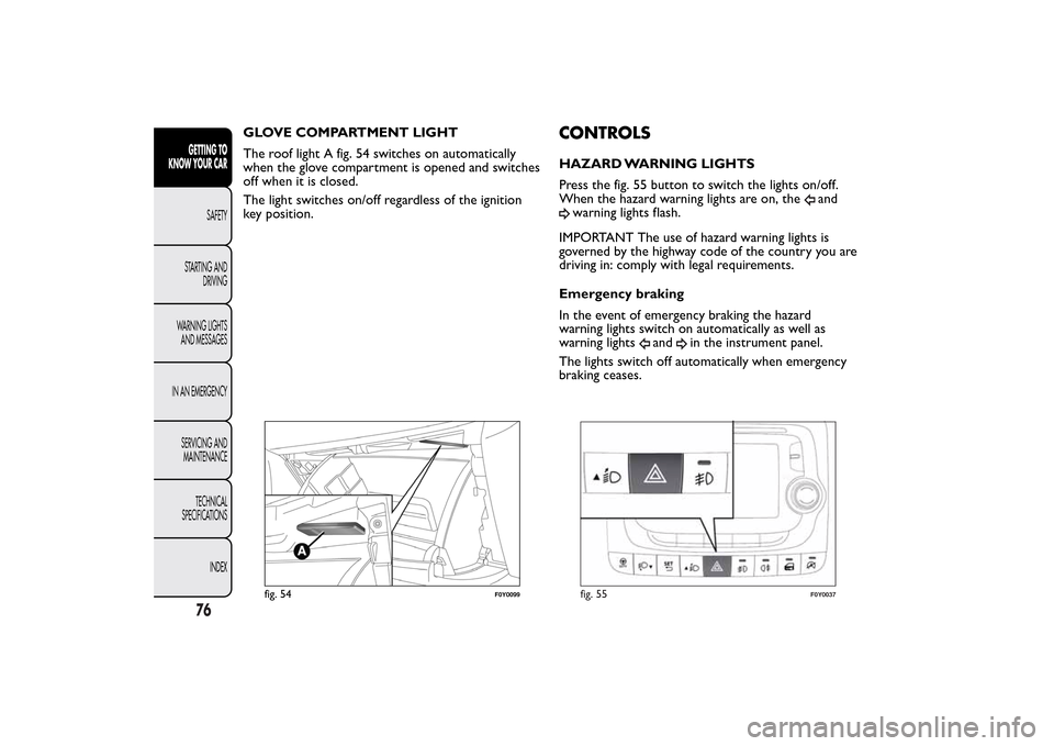
The roof light A fig. 54 switches on automatically
when the glove compartment is opened and switches
off when it is closed.
The light switches on/off regardless of the ignition
key position.
CONTROLSHAZARD WARNING LIGHTS
Press the fig. 55 button to switch the lights on/off.
When the hazard warning lights are on, the
and
warning lights flash.
IMPORTANT The use of hazard warning lights is
governed by the highway code of the country you are
driving in: comply with legal requirements.
Emergency braking
In the event of emergency braking the hazard
warning lights switch on automatically as well as
warning lights
and
in the instrument panel.
The lights switch off automatically when emergency
braking ceases.
fig. 54
F0Y0099
fig. 55
F0Y0037
76GETTING TO
KNOW YOUR CAR
SAFETY
STARTING AND
DRIVING
WARNING LIGHTS
AND MESSAGES
IN AN EMERGENCY
SERVICING AND
MAINTENANCE
TECHNICAL
SPECIFICATIONS
INDEX
Page 82 of 420
DUALDRIVE ELECTRIC POWER STEERING
(for versions/markets, where provided)
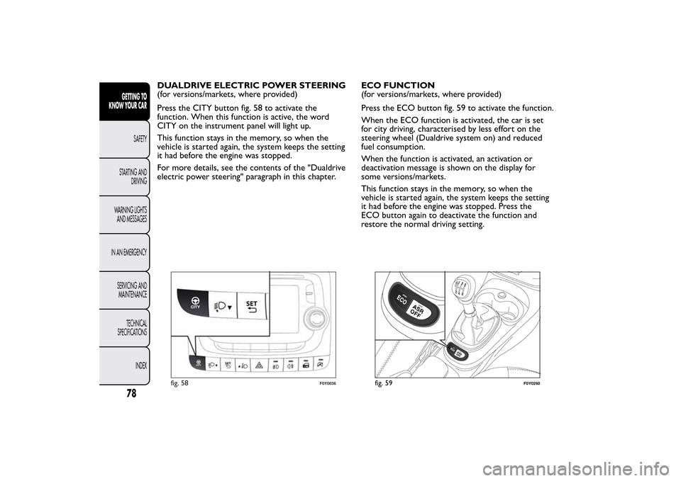
Press the CITY button fig. 58 to activate the
function. When this function is active, the word
CITY on the instrument panel will light up.
This function stays in the memory, so when the
vehicle is started again, the system keeps the setting
it had before the engine was stopped.
For more details, see the contents of the "Dualdrive
electric power steering" paragraph in this chapter.ECO FUNCTION
(for versions/markets, where provided)
Press the ECO button fig. 59 to activate the function.
When the ECO function is activated, the car is set
for city driving, characterised by less effort on the
steering wheel (Dualdrive system on) and reduced
fuel consumption.
When the function is activated, an activation or
deactivation message is shown on the display for
some versions/markets.
This function stays in the memory, so when the
vehicle is started again, the system keeps the setting
it had before the engine was stopped. Press the
ECO button again to deactivate the function and
restore the normal driving setting.
fig. 58
F0Y0036
fig. 59
F0Y0260
78GETTING TO
KNOW YOUR CAR
SAFETY
STARTING AND
DRIVING
WARNING LIGHTS
AND MESSAGES
IN AN EMERGENCY
SERVICING AND
MAINTENANCE
TECHNICAL
SPECIFICATIONS
INDEX
Page 96 of 420
PASSENGER SIDE FRONT DOOR AND
REAR DOOR EMERGENCY LOCKING
DEVICE
The passenger side front door and the rear doors
have a device to lock them when there is no
electrical power supply.
In this case proceed as follows:
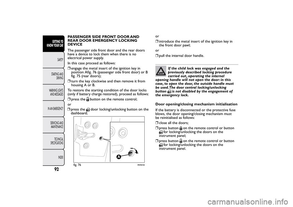
❒engage the metal insert of the ignition key in
position Afig. 76 (passenger side front door) or B
fig. 75 (rear doors);
❒turn the key clockwise and then remove it from
housing A or B.
To restore the starting condition of the door locks
(only if battery charge restored), proceed as follows:
❒press the
button on the remote control;
or
❒press thedoor locking/unlocking button on the
dashboard;or
❒introduce the metal insert of the ignition key in
the front door pawl;
or
❒pull the internal door handle.
If the child lock was engaged and the
previously described locking procedure
carried out , operating the internal
opening handle will not open the door: in this
case, to open the door, the outside handle must
be used.The door central locking/unlocking
button
is not disabled by the engagement of
the emergency lock.
Door opening/closing mechanism initialisation
If the battery is disconnected or the protective fuse
blows, the door opening/closing mechanism must
be reinitialised as follows:
❒close all the doors;
❒press button
on the remote control or button
for locking/unlocking the doors on the
instrument panel;
❒press button
on the remote control or button
for locking/unlocking the doors on the
instrument panel.
fig. 76
F0Y0110
92GETTING TO
KNOW YOUR CAR
SAFETY
STARTING AND
DRIVING
WARNING LIGHTS
AND MESSAGES
IN AN EMERGENCY
SERVICING AND
MAINTENANCE
TECHNICAL
SPECIFICATIONS
INDEX
Page 116 of 420
ESC SYSTEM
(Electronic Stability Control)This is an electronic system that controls car stability
in the event of tyre grip loss, helping maintain
directional control.
The system is capable of recognising potentially
dangerous situations in terms of the stability and
intervenes automatically on the brakes in a
differentiated manner for the four wheels in order to
provide a stabilising torque.
The ESC system also includes the following
subsystems:
❒Hill Holder
❒ASR
❒HBA
❒DST
❒ERM
SYSTEM INTERVENTION
It is signalled by the flashing of theESCwarning light
on the instrument panel, to inform the driver that
the car is in critical stability and grip conditions.
SYSTEM ACTIVATION
The ESC system switches on automatically when the
engine is started and cannot be switched off.HILL HOLDER SYSTEM
This system is an integral part of the ESC system and
facilitates starting on slopes.
It is activated automatically in the following instances:
❒uphill: car stationary on a road with a gradient
higher than 5%, engine running, brake pressed and
gearbox in neutral or gear (other than reverse)
engaged;
❒downhill: car stationary on a road with a gradient
higher than 5%, engine running, brake pressed and
reverse gear engaged.
When setting off, the ESC system control unit
maintains braking pressure on the wheels until the
torque required for starting is reach or, in any case,
for a maximum of 2 seconds so that the right foot
can be moved easily from the brake pedal to the
accelerator pedal.
When 2 seconds have elapsed, without any
departure having taken place, the system is
automatically deactivated, gradually releasing the
braking pressure. During this release stage, a typical
mechanical brake release noise can be heard,
indicating that the car is about to move.
IMPORTANT The Hill Holder system is not a parking
brake; therefore, never leave the vehicle without
having engaged the handbrake, turned the engine off
and engaged the 1
stgear, so that the vehicle is parked
in safe conditions (for further information read
paragraph "When parked" in the chapter "Starting
and driving").
112GETTING TO
KNOW YOUR CAR
SAFETY
STARTING AND
DRIVING
WARNING LIGHTS
AND MESSAGES
IN AN EMERGENCY
SERVICING AND
MAINTENANCE
TECHNICAL
SPECIFICATIONS
INDEX
Page 120 of 420
TRACTION PLUS SYSTEM(for versions/markets, where provided)
Traction Plus is a driving aid, useful for setting off in
poor grip conditions (snow, ice, mud, etc.), which
allows the drive force to be distributed optimally on
the front axle.
The activation of the Traction Plus system generates
the differential locking effect on the front axle
through the braking system, to optimise traction on
irregular terrain.
Traction Plus acts by braking the wheels with poor
grip (or those slipping more than the others),
thereby transferring the drive force to those which
have greater grip on the ground.
OPERATION
When the engine is started the system is
deactivated.
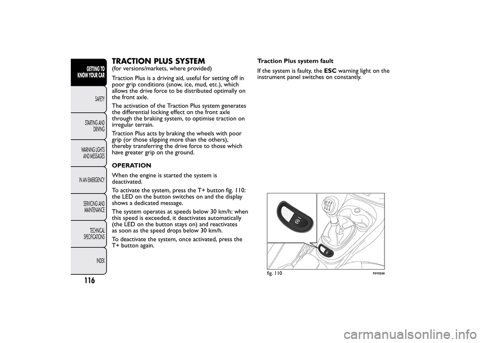
To activate the system, press the T+ button fig. 110:
the LED on the button switches on and the display
shows a dedicated message.
The system operates at speeds below 30 km/h: when
this speed is exceeded, it deactivates automatically
(the LED on the button stays on) and reactivates
as soon as the speed drops below 30 km/h.
To deactivate the system, once activated, press the
T+ button again.Traction Plus system fault
If the system is faulty, theESCwarning light on the
instrument panel switches on constantly.
fig. 110
F0Y0248
116GETTING TO
KNOW YOUR CAR
SAFETY
STARTING AND
DRIVING
WARNING LIGHTS
AND MESSAGES
IN AN EMERGENCY
SERVICING AND
MAINTENANCE
TECHNICAL
SPECIFICATIONS
INDEX
Page 123 of 420
SAFETY FUNCTIONS
When the engine is stopped by the Start&Stop
system, if the driver releases his/her seat belt and
opens the driver's or passenger's door, the engine
can be restarted only using the ignition key.
This condition is signalled to the driver with an
acoustic signal.
"ENERGY SAVING" FUNCTION
(for versions/markets, where provided)
If, following automatic engine restarting, the driver
does not carry out any action on the car for over
3 minutes, the Start&Stop system stops the engine
once and for all, to prevent fuel consumption.
In these cases, the engine can only be restarted using
the ignition key.
NoteIn any case, it is possible to keep the engine
running by deactivating the Start&Stop system.
IRREGULAR OPERATION
In the event of malfunction, the Start&Stop system is
deactivated.
Versions with multifunction display:a
Start&Stop system failure is indicated by the
switching on of the
warning light on the
instrument panel and a message on the display.
Versions with reconfigurable multifunction
display:The
symbol and a dedicated message
appear on the display when a failure in the
Start&Stop system is detected.In the event of a Start&Stop system failure, contact a
Fiat Dealership.
CAR INACTIVITY
In the event of car inactivity (or if the battery is
replaced), special attention must be paid to the
disconnection of the battery electrical system.
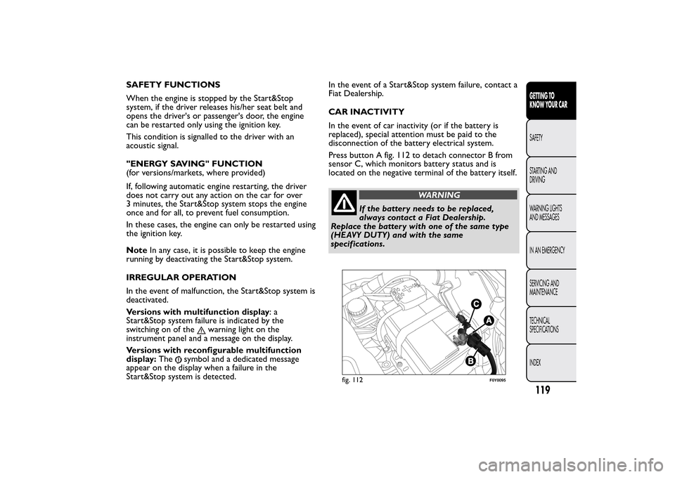
Press button A fig. 112 to detach connector B from
sensor C, which monitors battery status and is
located on the negative terminal of the battery itself.
WARNING
If the battery needs to be replaced,
always contact a Fiat Dealership.
Replace the battery with one of the same type
(HEAVY DUTY) and with the same
specifications.
fig. 112
F0Y0095
119GETTING TO
KNOW YOUR CARSAFETY
STARTING AND
DRIVING
WARNING LIGHTS
AND MESSAGES
IN AN EMERGENCY
SERVICING AND
MAINTENANCE
TECHNICAL
SPECIFICATIONS
INDEX
Page 132 of 420
EOBD SYSTEMThe EOBD system (European On Board Diagnosis)
carries out a continuous diagnosis of the
components of the car related to emissions. It also
alerts the driver, by turning on warning light
on
the instrument panel (together with a message
on the display on some versions), when these
components are no longer in peak condition (see
section “Warning lights and messages”).
The aim of the EOBD system (European On Board
Diagnosis) is to:
❒monitor the system efficiency;
❒indicate an increase in emissions;
❒indicate the need to replace damaged components.
The system also has a diagnosis connector that can
be interfaced to suitable instruments, to read the
error codes stored in the control unit together with
a series of specific parameters for engine operation
and diagnosis.
IMPORTANT After eliminating the failure, to check
the system completely, Fiat Dealerships run a bench
test and, if necessary, road tests which may also
call for a long journey.
DUALDRIVE ELECTRIC
POWER STEERINGThis only operates with the key turned to MAR and
the engine started. The steering allows the force
required at the steering wheel to be adjusted to suit
driving conditions.
IMPORTANT When turning the ignition key quickly,
full power steering functionality can be achieved after
a few seconds.
CITY FUNCTION ACTIVATION/
DEACTIVATION
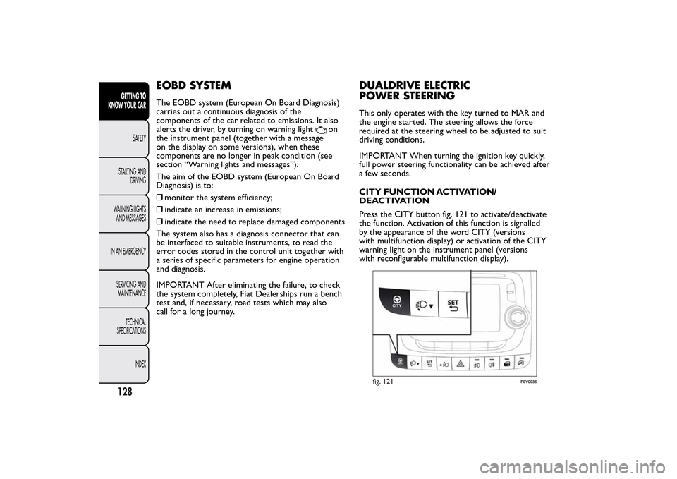
Press the CITY button fig. 121 to activate/deactivate
the function. Activation of this function is signalled
by the appearance of the word CITY (versions
with multifunction display) or activation of the CITY
warning light on the instrument panel (versions
with reconfigurable multifunction display).
fig. 121
F0Y0036
128GETTING TO
KNOW YOUR CAR
SAFETY
STARTING AND
DRIVING
WARNING LIGHTS
AND MESSAGES
IN AN EMERGENCY
SERVICING AND
MAINTENANCE
TECHNICAL
SPECIFICATIONS
INDEX
Page 138 of 420
ACOUSTIC SIGNAL
When reverse gear is engaged and there is an
obstacle behind the vehicle, an acoustic signal is
emitted which varies according to the distance of the
bumper from the obstacle.
The frequency of the acoustic signal:
❒increases as the distance between car and obstacle
decreases, culminating in a continuous acoustic
signal, when the distance is less than approximately
30 cm;
❒decreases if the distance from the obstacle
increases, until the signal ceases entirely;
❒remains constant if the distance between car and
obstacle remains unchanged; if this situation
concerns the side sensors, the signal will stop after
approximately 3 seconds to avoid, for example,
indications in the event of manoeuvres along
a wall.
If several obstacles are detected by the sensors, only
the nearest one is considered.FAULT INDICATION
Any parking sensor faults will be indicated when
reverse is engaged by the
warning light on the
instrument panel together with the message in the
multifunction display (for versions/markets, where
provided) (see “Warning lights and messages”
section).
OPERATION WITH TRAILER
Sensor operation is deactivated automatically when
the trailer's electric cable plug is fitted into the
car's tow hook socket.
The sensors are automatically reactivated when the
trailer's cable plug is removed.
For correct operation, sensors must always
be clean from mud, dirt , snow or ice. Be
careful not to scratch or damage the
sensors while cleaning them. Avoid using dry,
rough or hard cloths.The sensors should be
washed using clean water with the addition of car
shampoo if necessary.When using special
washing equipment such as high pressure jets or
steam cleaning, clean the sensors very quickly
keeping the jet more than 10 cm away. Also, do
not apply stickers to the sensors.
134GETTING TO
KNOW YOUR CAR
SAFETY
STARTING AND
DRIVING
WARNING LIGHTS
AND MESSAGES
IN AN EMERGENCY
SERVICING AND
MAINTENANCE
TECHNICAL
SPECIFICATIONS
INDEX