Page 7 of 420

GETTING TO KNOW YOUR CAR
DASHBOARDThe presence and position of the controls, instruments and indicators may vary according to the different
versions.1. Adjustable and directable air diffusers 2. Radio controls on the steering wheel (for versions/markets, where provided)
3. Exterior light control stalk 4. Instrument panel 5. Windscreen wiper/rear window wiper/trip computer control stalk
6. Adjustable and directable centre air vents 7. Fixed upper air vent 8. Passenger front airbag 9. Upper glove
compartment (for versions/markets, where provided the compartment may be conditioned) 10. Storage compartment
11. Lower glove compartment 12. Control buttons 13. Heating/ventilation system or manual climate control (for
versions/markets, where provided) or automatic dual zone climate control (for versions/markets, where provided)
14. USB port/AUX socket (for versions/markets, where provided) 15.
UConnect
vided) or radio system setup 16. Ignition switch 17. Driver front airbag 18. Cruise Control/Speed Limiter lever (for
versions/markets, where provided)
fig. 1
F0Y0042
3GETTING TO
KNOW YOUR CARSAFETY
STARTING AND
DRIVING
WARNING LIGHTS
AND MESSAGES
IN AN EMERGENCY
SERVICING AND
MAINTENANCE
TECHNICAL
SPECIFICATIONS
INDEX
™ (for versions/markets, where pro-
Page 129 of 420
 or people,
animals and things (e.g. pushchairs) and more in
general all those")
WARNING
The system intervenes on vehicles
travelling in the same lane. Small sized
vehicles (e.g. bicycles or motorbikes) or people,
animals and things (e.g. pushchairs) and more in
general all those obstacles with a low reflection
of the light emitted by the laser (e.g. vehicles
soiled with mud) are not taken into
consideration.If a trailer or a car is towed the system
must be deactivated with the display
Setup Menu (see paragraph "Menu
items" in this chapter).
WARNING
If the car must be placed on a roller
bench (at a speed within 5 and 30 km/h)
for maintenance interventions or if it is washed
in an automatic roller washing tunnel with an
obstacle in the front part (e.g. another car, a
wall or another obstacle), the system may
detect its presence and activate. In this case the
system must be deactivated with the display
setup menu (see paragraph “Menu items”
in this chapter).
REAR CAMERA (PARKVIEW®
REAR BACK UP CAMERA)(for versions/markets, where provided)
The camera is located on the tailgate fig. 119.
CAMERA ACTIVATION/DEACTIVATION
The camera is activated/deactivated through the
"Settings" menu of Uconnect™ 5" Radio or,
depending on the versions of the Uconnect™ 5"
Radio Nav (see "Safety/Assistance" in the "More
mode" paragraph).
When the camera is activated, whenever reverse is
engaged the display shows the image of the car
rear area fig. 120.
The image is displayed, together with a warning
message: after a few seconds, the message
disappears.
fig. 119
F0Y0336
125GETTING TO
KNOW YOUR CARSAFETY
STARTING AND
DRIVING
WARNING LIGHTS
AND MESSAGES
IN AN EMERGENCY
SERVICING AND
MAINTENANCE
TECHNICAL
SPECIFICATIONS
INDEX
Page 134 of 420

The car may be equipped with a dual storage
compartment fig. 122 on the dashboard.
The radio setup system is composed of:
❒radio supply leads")
RADIO SETUP SYSTEM(for versions/markets, where provided)
The car may be equipped with a dual storage
compartment fig. 122 on the dashboard.
The radio setup system is composed of:
❒radio supply leads;
❒no. 2 front tweeters
38 mm, located on the
door handle;
❒no. 2 mid-woofers165 mm, located on the door
panel;
❒no. 2 full-range speakers
165 mm, located on
the door panel;
❒radio housing;
❒aerial (on car roof ).
The radio can be installed in place of compartment A
fig. 122, which snaps into place and can be removed
by pulling it outwards. Having done this, the cables
provided are accessible.
For connection to the radio system set-up,
contact a Fiat Dealership to prevent any
problem that could impair car safety.
PREPARATION TO INSTALL A
PORTABLE NAVIGATION SYSTEMInstall the portable navigation system by fitting the
specific mounting bracket in the housing shown
in fig. 123.
fig. 122
F0Y0139
fig. 123
F0Y0132
130GETTING TO
KNOW YOUR CAR
SAFETY
STARTING AND
DRIVING
WARNING LIGHTS
AND MESSAGES
IN AN EMERGENCY
SERVICING AND
MAINTENANCE
TECHNICAL
SPECIFICATIONS
INDEX
Page 136 of 420
 or accessori")
ACCESSORIES PURCHASED
BY THE OWNERIf after buying the car, you decide to install electrical
accessories that require a permanent electric supply
(radio, satellite anti-theft system, etc.) or accessories
that in any case burden the electric supply, contact
a Fiat Dealership, whose qualified personnel, besides
suggesting the most suitable devices from
Lineaccessori Fiat, will also evaluate the overall
electric consumption, checking whether the car's
electrical system is able to withstand the load
required, or whether it needs to be integrated with a
more powerful battery.
WARNING
Take care when fitting additional
spoilers, alloy wheels or non-standard
wheel hubs: they could reduce the ventilation of
the brakes and affect efficiency under sharp,
repeated braking or on long descents. Make
sure that nothing obstructs the pedal stroke
(mats, etc .)INSTALLING ELECTRICAL/ELECTRONIC
DEVICES
Electrical and electronic devices installed after buying
the car in the context of after-sales service must
carry the label (see fig. 125):
Fiat Group Automobiles S.p.A. authorises the
installation of transceiver devices on condition that
such installations are carried out in a workmanlike
fashion, following the manufacturer’s instructions, at
a specialised centre.
IMPORTANT Traffic police may not allow the car on
the road if devices have been installed which modify
the features of the car. This may also cause
invalidation of warranty in relation to faults caused
by the change either directly or indirectly related
to it.
Fiat Group Automobiles S.p.A. shall not be liable for
damage caused by the installation of accessories
either not supplied or recommended by Fiat Group
Automobiles S.p.A. and/or not installed in
compliance with the provided instructions.
fig. 125
DISPOSITIVI-ELETTRONICI
132GETTING TO
KNOW YOUR CAR
SAFETY
STARTING AND
DRIVING
WARNING LIGHTS
AND MESSAGES
IN AN EMERGENCY
SERVICING AND
MAINTENANCE
TECHNICAL
SPECIFICATIONS
INDEX
Page 137 of 420
 cannot be used inside the car unless
a separate aerial is mounted externally.
IMPORTANT The use")
RADIO TRANSMITTERS AND MOBILE
PHONES
Radio transmitter equipment (vehicle mobile phones,
CB radios etc.) cannot be used inside the car unless
a separate aerial is mounted externally.
IMPORTANT The use of these devices inside the
passenger compartment (without an external aerial)
may cause the electrical systems to malfunction.
This could compromise the safety of the car in
addition to constituting a potential hazard for
passengers' health.
In addition, transmission and reception of these
devices may be negatively affected by the shielding
effect of the car body. As far as the use of
EC-approved mobile phones is concerned (GSM,
GPRS, UMTS), follow the usage instructions provided
by the mobile phone manufacturer.
PARKING SENSORS(for versions/markets, where provided)
They are located in the rear bumper fig. 126 and
their function is to detect the presence of any
obstacles near the rear part of the car; they
consequently inform the driver, through an
intermittent acoustic signal.
ACTIVATION/DEACTIVATION
The sensors are automatically activated when reverse
gear is engaged. As the obstacle behind the vehicle
gets closer to the car, the acoustic signal becomes
more frequent.
fig. 126
F0Y0140
133GETTING TO
KNOW YOUR CARSAFETY
STARTING AND
DRIVING
WARNING LIGHTS
AND MESSAGES
IN AN EMERGENCY
SERVICING AND
MAINTENANCE
TECHNICAL
SPECIFICATIONS
INDEX
Page 235 of 420
DASHBOARD FUSE BOX
fig. 203USERS FUSE AMPERE
Rear electric window (left side) F33 20
Rear electric window (right side) F34 20
Radio power supply (for versions/markets, where
provided), Uconnect™ 5" Radio, Uconnect™ 5" Radio
Nav, rear courtesy lights (right and left)F36 10
Central locking F38 20
Two-way windscreen washer pump F43 20
Front electric window (driver side) F47 20
Front electric window (passenger side) F48 20
Main beam headlight (left side) F90 7,5
Main beam headlight (right side) F91 7,5
Fog light (left side) F92 7,5
Fog light (right side) F93 7,5
231GETTING TO KNOW
YOUR CAR
SAFETY
STARTING AND
DRIVING
WARNING LIGHTS
AND MESSAGESIN AN
EMERGENCYSERVICING AND
MAINTENANCE
TECHNICAL
SPECIFICATIONS
INDEX
Page 296 of 420
RADIOFREQUENCY REMOTE CONTROL: MINISTERIAL APPROVALS
fig. 228
F0Y0277
292GETTING TO KNOW
YOUR CAR
SAFETY
STARTING AND
DRIVING
WARNING LIGHTS
AND MESSAGES
IN AN EMERGENCY
SERVICING AND
MAINTENANCE
TECHNICAL
SPECIFICATIONS
INDEX
Page 298 of 420
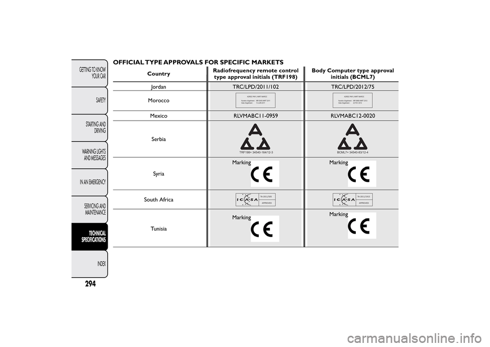
Morocco
��������
���
�������������������������������������������
�!��
"����
���
��������#�$%����������
��������
���
�������������&�'�����
���������������������
�!��
"����
���
��������#(#)����������
Mexico RLVMABC11-0959 RLVMABC12-0020
Serbia
TRF198= 34540-164/12-3
BCML7= 34540-83/12-4
SyriaMarking
Marking
South Africa
TA-2011/505
APPROVED
TA-2011/1915
APPROVED
TunisiaMarking
Marking
294GETTING TO KNOW
YOUR CAR
SAFETY
STARTING AND
DRIVING
WARNING LIGHTS
AND MESSAGES
IN AN EMERGENCY
SERVICING AND
MAINTENANCE
TECHNICAL
SPECIFICATIONS
INDEX
OFFICIAL TYPE APPROVALS FOR SPECIFIC MARKETS
CountryRadiofrequency remote control
type approval initials (TRF198)Body Computer type approval
initials (BCML7)
Jordan TRC/LPD/2011/102 TRC/LPD/2012/75
 F33 20
Rear electric window (right side) F34 20
Radio power supply (for versions/markets, where
provided), Uconnect™ 5\"")