2014 FIAT 500L LIVING wheel
[x] Cancel search: wheelPage 68 of 420
FLASHING
To do this, pull the stalk towards the steering wheel
(unstable position) regardless of the position of
ring nut A.
The
warning light switches on in the instrument
panel.
DIRECTION INDICATORS
Bring the stalk to the (stable) position:
upwards:right-hand direction indicator activation;
downwards:left-hand direction indicator activation.
Theor
warning light will flash on the
instrument panel.
Direction indicators are switched off automatically
when the steering wheel is straightened.
Lane change function
If you wish to signal a lane change, put the left stalk
in the unstable position for less than half a second.
The direction indicator on the side selected will
be activated for 5 flashes and then go out
automatically.
“Cornering lights”
When the dipped headlamps are on and the speed is
below 40 km/h, if the steering wheel rotation angle
is large or the direction indicators are on, a light
(incorporated in the fog light) will switch on on the
relevant side to improve visibility at nighttime.“FOLLOW ME HOME” DEVICE
This allows the space in front of the car to be lit up
for a certain period of time.
Activation: with the ignition key turned to STOP or
removed, pull the stalk towards the steering wheel
within 2 minutes from when the engine is turned off.
Each time the stalk is moved, the lights stay on for
an extra 30 seconds up to a maximum of 210
seconds; then the lights are switched off
automatically.
Also, each time the stalk is operated, the
warning light on the instrument panel switches
on. The display shows a message and the time set for
the function.
The
warning light switches on when the stalk is
first moved and stays on until the function is
automatically deactivated. Each movement of the
stalk only increases the amount of time the lights
stay on.
Deactivation: keep the stalk pulled towards the
steering wheel for more than two seconds.
64GETTING TO
KNOW YOUR CAR
SAFETY
STARTING AND
DRIVING
WARNING LIGHTS
AND MESSAGES
IN AN EMERGENCY
SERVICING AND
MAINTENANCE
TECHNICAL
SPECIFICATIONS
INDEX
Page 70 of 420
"Smart washing" function
Pull the lever towards the steering wheel (unstable
position) to activate the windscreen washer.
Keeping the stalk pulled for more than half a second,
with just one movement it is possible to operate
the washer jet and the wiper at the same time.
The wiper stops working three strokes after the
stalk is released.
A further stroke after approximately six seconds
completes the wiping cycle (for versions/markets,
where provided).
RAIN SENSOR
(for versions/markets, where provided)
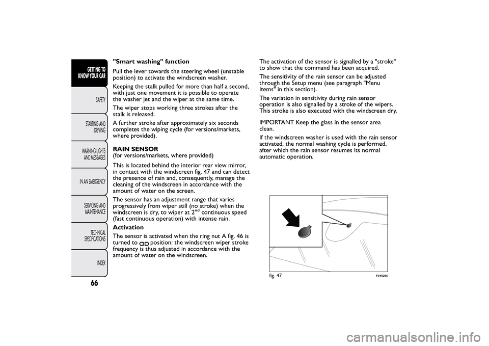
This is located behind the interior rear view mirror,
in contact with the windscreen fig. 47 and can detect
the presence of rain and, consequently, manage the
cleaning of the windscreen in accordance with the
amount of water on the screen.
The sensor has an adjustment range that varies
progressively from wiper still (no stroke) when the
windscreen is dry, to wiper at 2
nd
continuous speed
(fast continuous operation) with intense rain.
Activation
The sensor is activated when the ring nut A fig. 46 is
turned to
position: the windscreen wiper stroke
frequency is thus adjusted in accordance with the
amount of water on the windscreen.The activation of the sensor is signalled by a "stroke"
to show that the command has been acquired.
The sensitivity of the rain sensor can be adjusted
through the Setup menu (see paragraph "Menu
Items" in this section).
The variation in sensitivity during rain sensor
operation is also signalled by a stroke of the wipers.
This stroke is also executed with the windscreen dry.
IMPORTANT Keep the glass in the sensor area
clean.
If the windscreen washer is used with the rain sensor
activated, the normal washing cycle is performed,
after which the rain sensor resumes its normal
automatic operation.
fig. 47
F0Y0255
66GETTING TO
KNOW YOUR CAR
SAFETY
STARTING AND
DRIVING
WARNING LIGHTS
AND MESSAGES
IN AN EMERGENCY
SERVICING AND
MAINTENANCE
TECHNICAL
SPECIFICATIONS
INDEX
Page 82 of 420
DUALDRIVE ELECTRIC POWER STEERING
(for versions/markets, where provided)
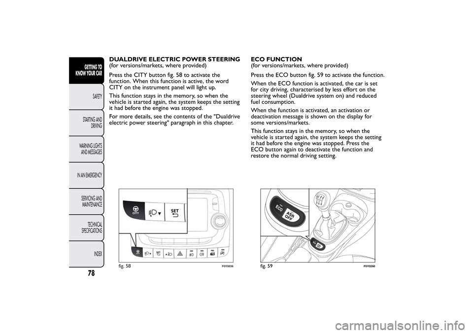
Press the CITY button fig. 58 to activate the
function. When this function is active, the word
CITY on the instrument panel will light up.
This function stays in the memory, so when the
vehicle is started again, the system keeps the setting
it had before the engine was stopped.
For more details, see the contents of the "Dualdrive
electric power steering" paragraph in this chapter.ECO FUNCTION
(for versions/markets, where provided)
Press the ECO button fig. 59 to activate the function.
When the ECO function is activated, the car is set
for city driving, characterised by less effort on the
steering wheel (Dualdrive system on) and reduced
fuel consumption.
When the function is activated, an activation or
deactivation message is shown on the display for
some versions/markets.
This function stays in the memory, so when the
vehicle is started again, the system keeps the setting
it had before the engine was stopped. Press the
ECO button again to deactivate the function and
restore the normal driving setting.
fig. 58
F0Y0036
fig. 59
F0Y0260
78GETTING TO
KNOW YOUR CAR
SAFETY
STARTING AND
DRIVING
WARNING LIGHTS
AND MESSAGES
IN AN EMERGENCY
SERVICING AND
MAINTENANCE
TECHNICAL
SPECIFICATIONS
INDEX
Page 84 of 420
INTERIOR FITTINGSSTORAGE COMPARTMENTS
Upper compartment
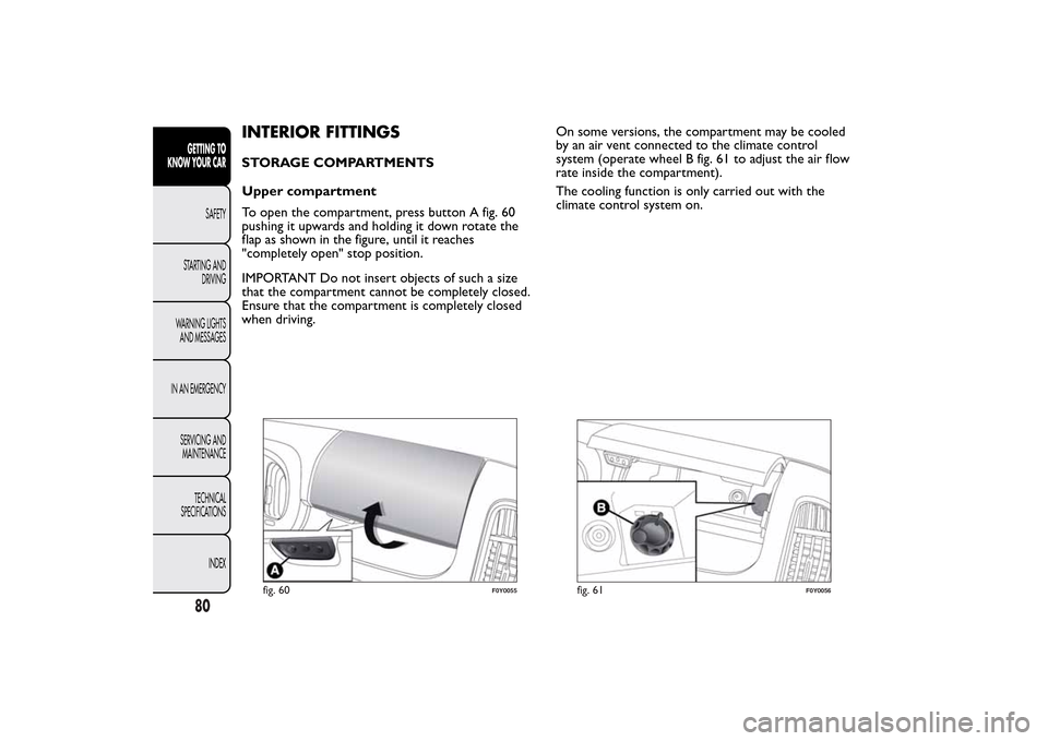
To open the compartment, press button A fig. 60
pushing it upwards and holding it down rotate the
flap as shown in the figure, until it reaches
"completely open" stop position.
IMPORTANT Do not insert objects of such a size
that the compartment cannot be completely closed.
Ensure that the compartment is completely closed
when driving.On some versions, the compartment may be cooled
by an air vent connected to the climate control
system (operate wheel B fig. 61 to adjust the air flow
rate inside the compartment).
The cooling function is only carried out with the
climate control system on.
fig. 60
F0Y0055
fig. 61
F0Y0056
80GETTING TO
KNOW YOUR CAR
SAFETY
STARTING AND
DRIVING
WARNING LIGHTS
AND MESSAGES
IN AN EMERGENCY
SERVICING AND
MAINTENANCE
TECHNICAL
SPECIFICATIONS
INDEX
Page 108 of 420
Moving the load platform
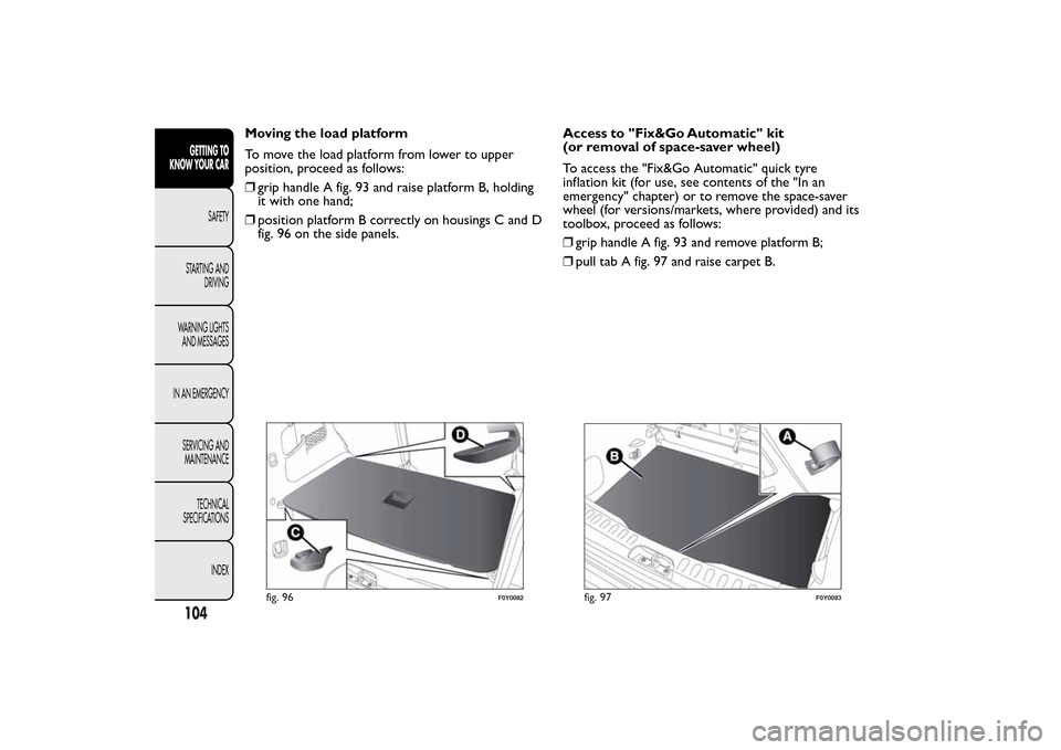
To move the load platform from lower to upper
position, proceed as follows:
❒grip handle A fig. 93 and raise platform B, holding
it with one hand;
❒position platform B correctly on housings C and D
fig. 96 on the side panels.Access to "Fix&Go Automatic" kit
(or removal of space-saver wheel)
To access the "Fix&Go Automatic" quick tyre
inflation kit (for use, see contents of the "In an
emergency" chapter) or to remove the space-saver
wheel (for versions/markets, where provided) and its
toolbox, proceed as follows:
❒grip handle A fig. 93 and remove platform B;
❒pull tab A fig. 97 and raise carpet B.
fig. 96
F0Y0082
fig. 97
F0Y0083
104GETTING TO
KNOW YOUR CAR
SAFETY
STARTING AND
DRIVING
WARNING LIGHTS
AND MESSAGES
IN AN EMERGENCY
SERVICING AND
MAINTENANCE
TECHNICAL
SPECIFICATIONS
INDEX
Page 114 of 420
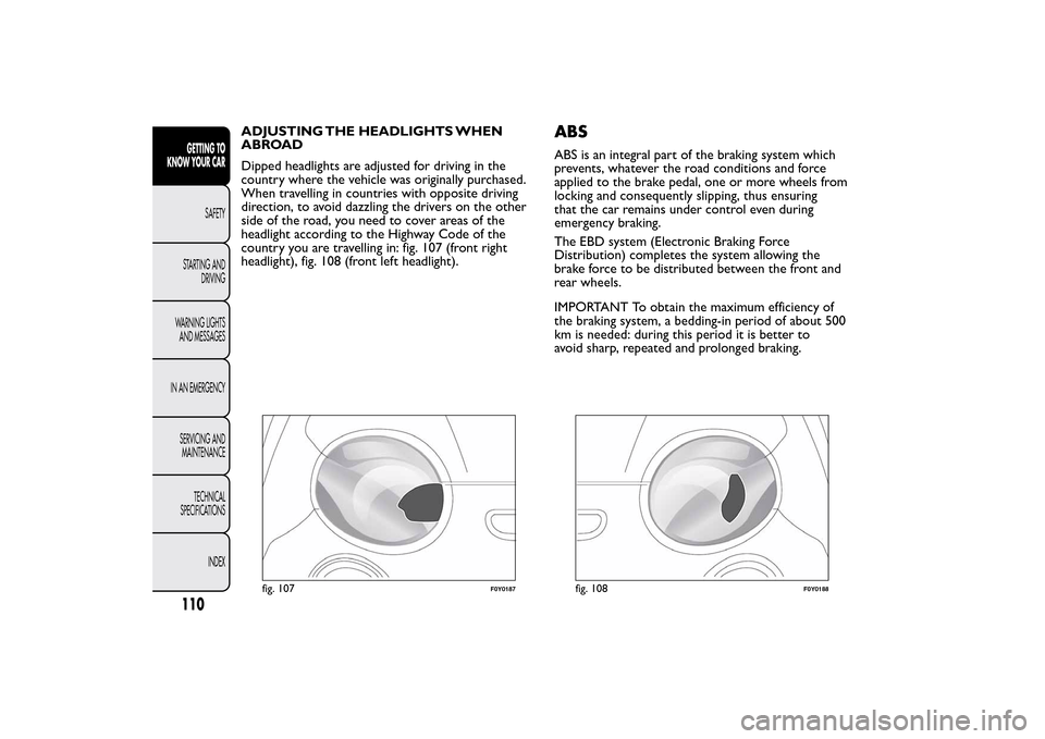
ADJUSTING THE HEADLIGHTS WHEN
ABROAD
Dipped headlights are adjusted for driving in the
country where the vehicle was originally purchased.
When travelling in countries with opposite driving
direction, to avoid dazzling the drivers on the other
side of the road, you need to cover areas of the
headlight according to the Highway Code of the
country you are travelling in: fig. 107 (front right
headlight), fig. 108 (front left headlight).
ABSABS is an integral part of the braking system which
prevents, whatever the road conditions and force
applied to the brake pedal, one or more wheels from
locking and consequently slipping, thus ensuring
that the car remains under control even during
emergency braking.
The EBD system (Electronic Braking Force
Distribution) completes the system allowing the
brake force to be distributed between the front and
rear wheels.
IMPORTANT To obtain the maximum efficiency of
the braking system, a bedding-in period of about 500
km is needed: during this period it is better to
avoid sharp, repeated and prolonged braking.
fig. 107
F0Y0187
fig. 108
F0Y0188
110GETTING TO
KNOW YOUR CAR
SAFETY
STARTING AND
DRIVING
WARNING LIGHTS
AND MESSAGES
IN AN EMERGENCY
SERVICING AND
MAINTENANCE
TECHNICAL
SPECIFICATIONS
INDEX
Page 115 of 420
WARNING
The ABS gets the most from the
available grip, but it cannot improve it ;
you should therefore take every care when
driving on slippery surfaces and not take
unnecessary risks.
SYSTEM INTERVENTION
The driver can feel that the ABS system has come
into action because the brake pedal pulsates slightly
and the system gets noisier: it means that the speed
should be altered to suit the type of road surface.
WARNING
When the ABS cuts in and you feel the
brake pedal pulsating, do not raise
your foot , but keep it pressed; in doing so you
will stop in the shortest amount of space
possible depending on the current road
conditions.
WARNING
If the ABS system intervenes, this
indicates that the traction of the tyres
on the road is nearing its limit .You must slow
down to a speed compatible with the available
traction.MSR SYSTEM
(Motor Schleppmoment Regelung)
This system is an integral part of the ABS, that
intervenes, if there is sudden downshifting, restoring
torque to the engine, thereby preventing excessive
drive at the drive wheels which, especially in poor
grip conditions, could lead to a loss in stability of the
car.
111GETTING TO
KNOW YOUR CARSAFETY
STARTING AND
DRIVING
WARNING LIGHTS
AND MESSAGES
IN AN EMERGENCY
SERVICING AND
MAINTENANCE
TECHNICAL
SPECIFICATIONS
INDEX
Page 116 of 420
ESC SYSTEM
(Electronic Stability Control)This is an electronic system that controls car stability
in the event of tyre grip loss, helping maintain
directional control.
The system is capable of recognising potentially
dangerous situations in terms of the stability and
intervenes automatically on the brakes in a
differentiated manner for the four wheels in order to
provide a stabilising torque.
The ESC system also includes the following
subsystems:
❒Hill Holder
❒ASR
❒HBA
❒DST
❒ERM
SYSTEM INTERVENTION
It is signalled by the flashing of theESCwarning light
on the instrument panel, to inform the driver that
the car is in critical stability and grip conditions.
SYSTEM ACTIVATION
The ESC system switches on automatically when the
engine is started and cannot be switched off.HILL HOLDER SYSTEM
This system is an integral part of the ESC system and
facilitates starting on slopes.
It is activated automatically in the following instances:
❒uphill: car stationary on a road with a gradient
higher than 5%, engine running, brake pressed and
gearbox in neutral or gear (other than reverse)
engaged;
❒downhill: car stationary on a road with a gradient
higher than 5%, engine running, brake pressed and
reverse gear engaged.
When setting off, the ESC system control unit
maintains braking pressure on the wheels until the
torque required for starting is reach or, in any case,
for a maximum of 2 seconds so that the right foot
can be moved easily from the brake pedal to the
accelerator pedal.
When 2 seconds have elapsed, without any
departure having taken place, the system is
automatically deactivated, gradually releasing the
braking pressure. During this release stage, a typical
mechanical brake release noise can be heard,
indicating that the car is about to move.
IMPORTANT The Hill Holder system is not a parking
brake; therefore, never leave the vehicle without
having engaged the handbrake, turned the engine off
and engaged the 1
stgear, so that the vehicle is parked
in safe conditions (for further information read
paragraph "When parked" in the chapter "Starting
and driving").
112GETTING TO
KNOW YOUR CAR
SAFETY
STARTING AND
DRIVING
WARNING LIGHTS
AND MESSAGES
IN AN EMERGENCY
SERVICING AND
MAINTENANCE
TECHNICAL
SPECIFICATIONS
INDEX