2014 FIAT 500L LIVING maintenance reset
[x] Cancel search: maintenance resetPage 22 of 420
Warnings volume
(Adjusting the alert/warning acoustic signal
volume)
With this function the volume of the buzzer which
accompanies the display of any failure/warning can be
adjusted to 8 levels.
To set the desired volume, proceed as follows:
❒press button
briefly. The volume “level” set
previously flashes on the display;
❒press
or
to make your choice;
❒press the
button briefly to return to the menu
screen or hold the button down to return to the
standard screen without storing.
Seat belt buzzer
(SBR buzzer reactivation)
This function can only be displayed after a Fiat
Dealership has deactivated the SBR system (see
paragraph “SBR system” in the “Safety” chapter).
To reactivate this function, proceed as follows:
❒press thebutton briefly; "Off" will flash on the
display. Press the
or
button and "On"
will appear;
❒press the
button briefly to return to the
submenu screen or hold the button down
to return to the main menu screen without saving.Service (Scheduled servicing)
With this function it is possible to view information
on mileage or time intervals for servicing.
To consult this display, proceed as follows:
❒press button
briefly. The display shows the
service interval in kilometres (km) or miles (mi)
according to the previous setting (see the "Units of
measurement" paragraph);
❒press the
button briefly to return to the menu
screen or hold it down to return to the standard
screen.
18GETTING TO
KNOW YOUR CAR
SAFETY
STARTING AND
DRIVING
WARNING LIGHTS
AND MESSAGES
IN AN EMERGENCY
SERVICING AND
MAINTENANCE
TECHNICAL
SPECIFICATIONS
INDEX
NoteThe “Scheduled Servicing Plan” includes car
maintenance at fixed intervals, refer to the
"Maintenance and care" chapter. This message is
displayed automatically - when the key is turned to
MAR-ON - 2,000 km (or equivalent value in miles)
before these deadlines and reappears every 200
km (or equivalent value in miles). Below 200 km
servicing indications are more frequent. The display
will be in km or mi depending on the measurement
unit settings. When one of the next scheduled
deadlines is approaching, the word “Service” will
appear on the display, followed by the number of
kilometres or miles left, when the key is turned to
MAR-ON. Contact a Fiat Dealership. The operations
in the “Scheduled servicing plan” will be performed
and the message will be reset.
Page 24 of 420
Exit menu
The last function closing the cycle of settings listed in
the menu screen.
Pressing the
button briefly will return the display
to the standard screen without saving.
Press thebutton to return to the first menu
option (Lighting).
TRIP COMPUTERGENERAL INFORMATION
The Trip computer is used to display information on
car operation when the key is turned to MAR-ON.
This function allows you to define two separate trips
called “Trip A” and “Trip B” where the car's
"complete journeys" are monitored in a reciprocally
independent manner.
Both journeys can be reset (reset - start of a new
journey).
“Trip A” is used to display the figures relating to:
❒Outside temperature (for versions/markets, where
provided)
❒Range
❒Distance travelled A
❒Average consumption A
❒Instantaneous consumption
❒Average speed A
❒Trip time A (driving time).
“Trip B” may be used to display the figures relating
to:
❒Distance travelled B
❒Average consumption B
❒Average speed B
❒Trip time B (driving time).
20GETTING TO
KNOW YOUR CAR
SAFETY
STARTING AND
DRIVING
WARNING LIGHTS
AND MESSAGES
IN AN EMERGENCY
SERVICING AND
MAINTENANCE
TECHNICAL
SPECIFICATIONS
INDEX
Page 25 of 420
Note“Trip B” may be disabled (see “Activating Trip
B”). “Range” and “Instantaneous fuel consumption"
parameters cannot be reset.
VALUES DISPLAYED
Outside temperature (for versions/markets, where
provided)
Indicates the temperature outside the passenger
compartment.
Range
This indicates the approximate distance which can be
travelled with the amount of fuel present in the
tank.“----”will appear on the display in the
following cases:
❒range value lower than 50 km (or 30 mi)
❒car parked with engine running for a long period.
IMPORTANT The range value variation can be
affected by several factors: driving style, type of route
(motorway, urban, mountain roads, etc.), conditions
of use (load, tyre pressures, etc.). Trip planning
must therefore take the above into account.
Distance travelled
Shows the distance covered since the start of the
new journey.Average consumption
Shows the approximate average fuel consumption
since the start of the new journey.
Instantaneous consumption
This value shows the fuel consumption. The value is
constantly updated. The display will show “----”
if the car is parked with the engine running.
Average speed
This shows the car average speed as a function of the
overall time elapsed since the start of the new
mission.
Tr i p t i me
Shows the time elapsed since the start of a new
journey.
IMPORTANT If there is no information, the Trip
computer displays "----"inplaceofthevalue.
When normal operating condition is restored,
calculation of different units will restart regularly. No
values displayed before the failure will be reset nor
will a new mission be started.
21GETTING TO
KNOW YOUR CARSAFETY
STARTING AND
DRIVING
WARNING LIGHTS
AND MESSAGES
IN AN EMERGENCY
SERVICING AND
MAINTENANCE
TECHNICAL
SPECIFICATIONS
INDEX
Page 27 of 420
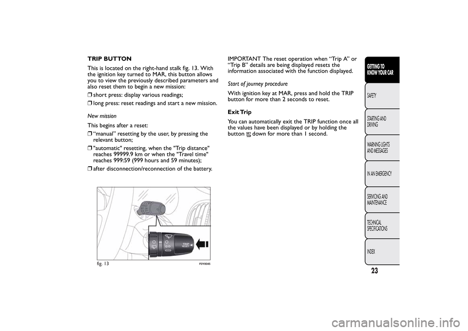
TRIP BUTTON
This is located on the right-hand stalk fig. 13. With
the ignition key turned to MAR, this button allows
you to view the previously described parameters and
also reset them to begin a new mission:
❒short press: display various readings;
❒long press: reset readings and start a new mission.
New mission
This begins after a reset:
❒“manual” resetting by the user, by pressing the
relevant button;
❒"automatic" resetting, when the "Trip distance"
reaches 99999.9 km or when the "Travel time"
reaches 999:59 (999 hours and 59 minutes);
❒after disconnection/reconnection of the battery.IMPORTANT The reset operation when “Trip A” or
“Trip B” details are being displayed resets the
information associated with the function displayed.
Start of journey procedure
With ignition key at MAR, press and hold the TRIP
button for more than 2 seconds to reset.
Exit Trip
You can automatically exit the TRIP function once all
the values have been displayed or by holding the
button
down for more than 1 second.
fig. 13
F0Y0045
23GETTING TO
KNOW YOUR CARSAFETY
STARTING AND
DRIVING
WARNING LIGHTS
AND MESSAGES
IN AN EMERGENCY
SERVICING AND
MAINTENANCE
TECHNICAL
SPECIFICATIONS
INDEX
Page 62 of 420
CLIMATE CONTROL SYSTEM
COMPRESSOR
Press button D to activate/deactivate the
compressor (activation is indicated by the LED on
the button switching on).
The system remembers that the compressor has
been switched off, even after the engine has stopped.
When the compressor is switched off the system
deactivates air recirculation to prevent the windows
from misting up. In this case, if the system is capable
of maintaining the required temperature, the AUTO
LED does not switch off.
The temperatures will instead flash for a few seconds
and the AUTO LED will switch off if the required
temperature cannot be maintained.
To restore automatic control of compressor
engagement, press button C again or press the
AUTO button.
With compressor off:
❒if the outside temperature is higher than the set
one, the climate control system will not be able
to satisfy the request. The temperature values will
then flash on the display for a few seconds to
indicate this;
❒the fan speed can be reset manually.
With the compressor on and the engine running,
manual ventilation cannot be lower than the
minimum speed (only one LED lit).IMPORTANT With the compressor off, air cannot
be introduced to the passenger compartment with a
temperature lower than the outside temperature.
Moreover, under certain environmental conditions,
windows could mist rapidly since the air is not
dehumidified.
RAPID WINDOW DEMISTING/
DEFROSTING (MAX-DEF function)
Press the
button to activate (LED on button on)
the windscreen and side window demisting/
defrosting function.
The climate control system carries out the following
operations:
❒switches on the air conditioning compressor when
environmental conditions are suitable;
❒switches air recirculation off;
❒sets maximum air temperature (HI) in both zones;
❒sets fan speed according to the engine coolant
temperature;
❒directs air flow to windscreen and front side
windows diffusers;
❒activates the heated rear window;
❒activates the heated windscreen (for versions/
markets, where provided);
❒displays the fan speed (LED G lit).
IMPORTANT The MAX-DEF function remains on for
about 3 minutes from when the engine coolant
reaches the appropriate temperature.
58GETTING TO
KNOW YOUR CAR
SAFETY
STARTING AND
DRIVING
WARNING LIGHTS
AND MESSAGES
IN AN EMERGENCY
SERVICING AND
MAINTENANCE
TECHNICAL
SPECIFICATIONS
INDEX
Page 180 of 420
Any electric brake or other device (winch etc.)
should be powered directly by the battery through a
cable with a cross-section of no less than 2.5 mm
2.
In addition to the electrical branches, the car's
electrical system can be connected only to the supply
cable for an electric brake and to the cable for an
internal trailer light, though not more than 15 W. To
connect, use the preset control unit with a battery
cable with cross-section no less than 2.5 mm
2.
IMPORTANT The use of auxiliary loads other than
external lights (electric brake, winch, etc.) must
occur with engine running.
IMPORTANT To install a tow hook contact a Fiat
Dealership.
WARNING
The ABS with which the car may be
equipped will not control the braking
system of the trailer. Particular caution is
required on slippery roads.
WARNING
Never modify the braking system of the
car to control the trailer brake.The
trailer braking system must be fully
independent of the car ’s hydraulic system.INSTALLING A TOW HOOK
The towing device should be fastened to the body by
specialised personnel according to any additional
and/or integrative information supplied by the
Manufacturer of the device.
The towing device must meet current regulations
with reference to Directive 94/20/EC and subsequent
amendments.
For any version the towing device used must be right
for the towable weight of the car on which it is to
be installed.
For the electrical connection a standard connector
should be used which is generally placed on a special
bracket normally fastened to the towing device,
and a special ECU for external trailer light control
must be installed on the car.
7 or 13-pin 12 V DC connections should be used
(CUNA/UNI and ISO/DIN Standards). Follow any
instructions provided by the car manufacturer and/or
the towing device manufacturer.
Installation diagram for basic versions fig. 151
The tow hook structure must be fastened in the
points shown in the figure with a total amount of 8
fastening points to the body.
176GETTING TO KNOW
YOUR CAR
SAFETYSTARTING AND
DRIVINGWARNING LIGHTS
AND MESSAGES
IN AN EMERGENCY
SERVICING AND
MAINTENANCE
TECHNICAL
SPECIFICATIONS
INDEX
Page 192 of 420
ESC SYSTEM FAILURE (amber)
(for versions/markets, where provided)
Turning the key to the MAR-ON position illuminates
the warning light, but it should switch off after a
few seconds.
If the warning light does not switch off or remains on
(together with a message and a symbol on the
display on some versions) whilst driving, contact a
Fiat Dealership.
Flashing of the warning light whilst driving indicates
the action of the ESC system.
Hill Holder failure
This warning light comes on, on some versions
together with the
symbol and a message in the
display, in the event of a fault with the Hill Holder
system. In this case, contact a Fiat Dealership.
Traction Plus failure
(for versions/markets, where provided)
If the Traction Plus system is faulty, theESCwarning
light on the instrument panel switches on
constantly.
FIAT CODE SYSTEM FAILURE
(amber)
(for versions/markets, where provided)
The warning light switches on (on some versions,
together with a message and a symbol on the display)
to indicate a Fiat CODE system failure: in this case
contact a Fiat Dealership as soon as possible.GLOW PLUG HEATING/GLOW
PLUG HEATING FAILURE (Diesel
versions) (amber)
GLOW PLUG HEATING
This warning light switches on when the key is
turned to MAR-ON. It will switch off as soon as the
heater plugs have reached the preset temperature.
The engine can be started as soon as the warning
light switches off.
IMPORTANT At high ambient temperatures the
warning light may stay on for an extremely short
time.
GLOW PLUG HEATING FAILURE
The warning light will flash (on some versions,
together with a message and a symbol on the display)
to indicate a fault in the plug preheating system.
Contact a Fiat Dealership to have the fault fixed as
soon as possible.
188GETTING TO KNOW
YOUR CAR
SAFETY
STARTING AND
DRIVINGWARNING LIGHTS
AND MESSAGESIN AN EMERGENCY
SERVICING AND
MAINTENANCE
TECHNICAL
SPECIFICATIONS
INDEX