2014 FIAT 500L LIVING turn signal
[x] Cancel search: turn signalPage 22 of 420
Warnings volume
(Adjusting the alert/warning acoustic signal
volume)
With this function the volume of the buzzer which
accompanies the display of any failure/warning can be
adjusted to 8 levels.
To set the desired volume, proceed as follows:
❒press button
briefly. The volume “level” set
previously flashes on the display;
❒press
or
to make your choice;
❒press the
button briefly to return to the menu
screen or hold the button down to return to the
standard screen without storing.
Seat belt buzzer
(SBR buzzer reactivation)
This function can only be displayed after a Fiat
Dealership has deactivated the SBR system (see
paragraph “SBR system” in the “Safety” chapter).
To reactivate this function, proceed as follows:
❒press thebutton briefly; "Off" will flash on the
display. Press the
or
button and "On"
will appear;
❒press the
button briefly to return to the
submenu screen or hold the button down
to return to the main menu screen without saving.Service (Scheduled servicing)
With this function it is possible to view information
on mileage or time intervals for servicing.
To consult this display, proceed as follows:
❒press button
briefly. The display shows the
service interval in kilometres (km) or miles (mi)
according to the previous setting (see the "Units of
measurement" paragraph);
❒press the
button briefly to return to the menu
screen or hold it down to return to the standard
screen.
18GETTING TO
KNOW YOUR CAR
SAFETY
STARTING AND
DRIVING
WARNING LIGHTS
AND MESSAGES
IN AN EMERGENCY
SERVICING AND
MAINTENANCE
TECHNICAL
SPECIFICATIONS
INDEX
NoteThe “Scheduled Servicing Plan” includes car
maintenance at fixed intervals, refer to the
"Maintenance and care" chapter. This message is
displayed automatically - when the key is turned to
MAR-ON - 2,000 km (or equivalent value in miles)
before these deadlines and reappears every 200
km (or equivalent value in miles). Below 200 km
servicing indications are more frequent. The display
will be in km or mi depending on the measurement
unit settings. When one of the next scheduled
deadlines is approaching, the word “Service” will
appear on the display, followed by the number of
kilometres or miles left, when the key is turned to
MAR-ON. Contact a Fiat Dealership. The operations
in the “Scheduled servicing plan” will be performed
and the message will be reset.
Page 28 of 420
SYMBOLSSpecial coloured labels have been attached near to or
on some of the components of your car. These
labels bear symbols that remind you of the
precautions to be taken with regard to that
particular component.
Under the bonnet there is also a label that
summarises all the symbols.
THE FIAT CODE SYSTEMTo further protect your car from theft, it has been
fitted with an engine immobilising system. It is
automatically activated when the ignition key is
removed.
There is an electronic device in each key which can
identify the signal emitted, when the engine is
started, from an aerial built into the ignition switch.
The signal is the "password", different every time the
vehicle is started, through which the control unit
recognises the key and enables starting.
OPERATION
Each time the vehicle is started turning the ignition
key to MAR-ON, the Fiat CODE system control unit
sends an acknowledgement code to the engine
control unit to deactivate the immobiliser. The code
is sent only if the Fiat CODE system control unit
has acknowledged the code received from the key.
Each time the ignition key is turned to STOP, the Fiat
CODE system deactivates the functions of the
engine management control unit.
If, during starting, the code is not correctly
recognised, the
warning light switches on in the
instrument panel.
In this case, turn the key to STOP and then to
MAR-ON; if it is still locked, try again with the other
keys that come with the vehicle. Contact a Fiat
Dealership if you still cannot start the engine.
24GETTING TO
KNOW YOUR CAR
SAFETY
STARTING AND
DRIVING
WARNING LIGHTS
AND MESSAGES
IN AN EMERGENCY
SERVICING AND
MAINTENANCE
TECHNICAL
SPECIFICATIONS
INDEX
Page 61 of 420
MONO BUTTON
Press the MONO button (LED on button lit) to align
the passenger side air temperature with that of the
driver side.
This function makes temperature regulation easier
when the driver is travelling alone.
Turn knob L to set the passenger side temperature
and return to separate air temperature management.
AIR RECIRCULATION
The air recirculation is managed according to the
following operating logics:
❒forced activation (air recirculation always on):
indicated by the LED on button B
;
❒forced deactivation (air recirculation always off, air
intake from the outside), signalled by the LED on
button B
switching off.
Forced activation/deactivation can be selected by
pressing button B
.
When button
is pressed, the climate control
system automatically activates internal air
recirculation (LED on button B
on)
It is still possible to activate outside air recirculation
(LED on the button off ) and vice versa, by pressing
button B
.In automatic operation, recirculation is managed
automatically by the system according to outside
environmental conditions.
IMPORTANT The engagement of the recirculation
system makes it possible to reach the required
heating/cooling conditions faster. It is, however,
inadvisable to use it on rainy/cold days as it would
considerably increase the possibility of the windows
misting up inside (especially if the climate control
system is off ). When the outside temperature is low,
recirculation is forced off (air drawn in from the
outside) to prevent the windows from misting up.
It is inadvisable to use internal air
recirculation when the outside
temperature is low, since the windows
could mist up rapidly.
57GETTING TO
KNOW YOUR CARSAFETY
STARTING AND
DRIVING
WARNING LIGHTS
AND MESSAGES
IN AN EMERGENCY
SERVICING AND
MAINTENANCE
TECHNICAL
SPECIFICATIONS
INDEX
Page 68 of 420
FLASHING
To do this, pull the stalk towards the steering wheel
(unstable position) regardless of the position of
ring nut A.
The
warning light switches on in the instrument
panel.
DIRECTION INDICATORS
Bring the stalk to the (stable) position:
upwards:right-hand direction indicator activation;
downwards:left-hand direction indicator activation.
Theor
warning light will flash on the
instrument panel.
Direction indicators are switched off automatically
when the steering wheel is straightened.
Lane change function
If you wish to signal a lane change, put the left stalk
in the unstable position for less than half a second.
The direction indicator on the side selected will
be activated for 5 flashes and then go out
automatically.
“Cornering lights”
When the dipped headlamps are on and the speed is
below 40 km/h, if the steering wheel rotation angle
is large or the direction indicators are on, a light
(incorporated in the fog light) will switch on on the
relevant side to improve visibility at nighttime.“FOLLOW ME HOME” DEVICE
This allows the space in front of the car to be lit up
for a certain period of time.
Activation: with the ignition key turned to STOP or
removed, pull the stalk towards the steering wheel
within 2 minutes from when the engine is turned off.
Each time the stalk is moved, the lights stay on for
an extra 30 seconds up to a maximum of 210
seconds; then the lights are switched off
automatically.
Also, each time the stalk is operated, the
warning light on the instrument panel switches
on. The display shows a message and the time set for
the function.
The
warning light switches on when the stalk is
first moved and stays on until the function is
automatically deactivated. Each movement of the
stalk only increases the amount of time the lights
stay on.
Deactivation: keep the stalk pulled towards the
steering wheel for more than two seconds.
64GETTING TO
KNOW YOUR CAR
SAFETY
STARTING AND
DRIVING
WARNING LIGHTS
AND MESSAGES
IN AN EMERGENCY
SERVICING AND
MAINTENANCE
TECHNICAL
SPECIFICATIONS
INDEX
Page 70 of 420
"Smart washing" function
Pull the lever towards the steering wheel (unstable
position) to activate the windscreen washer.
Keeping the stalk pulled for more than half a second,
with just one movement it is possible to operate
the washer jet and the wiper at the same time.
The wiper stops working three strokes after the
stalk is released.
A further stroke after approximately six seconds
completes the wiping cycle (for versions/markets,
where provided).
RAIN SENSOR
(for versions/markets, where provided)
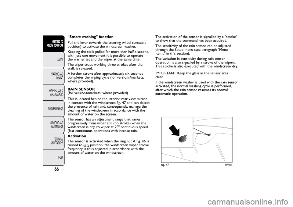
This is located behind the interior rear view mirror,
in contact with the windscreen fig. 47 and can detect
the presence of rain and, consequently, manage the
cleaning of the windscreen in accordance with the
amount of water on the screen.
The sensor has an adjustment range that varies
progressively from wiper still (no stroke) when the
windscreen is dry, to wiper at 2
nd
continuous speed
(fast continuous operation) with intense rain.
Activation
The sensor is activated when the ring nut A fig. 46 is
turned to
position: the windscreen wiper stroke
frequency is thus adjusted in accordance with the
amount of water on the windscreen.The activation of the sensor is signalled by a "stroke"
to show that the command has been acquired.
The sensitivity of the rain sensor can be adjusted
through the Setup menu (see paragraph "Menu
Items" in this section).
The variation in sensitivity during rain sensor
operation is also signalled by a stroke of the wipers.
This stroke is also executed with the windscreen dry.
IMPORTANT Keep the glass in the sensor area
clean.
If the windscreen washer is used with the rain sensor
activated, the normal washing cycle is performed,
after which the rain sensor resumes its normal
automatic operation.
fig. 47
F0Y0255
66GETTING TO
KNOW YOUR CAR
SAFETY
STARTING AND
DRIVING
WARNING LIGHTS
AND MESSAGES
IN AN EMERGENCY
SERVICING AND
MAINTENANCE
TECHNICAL
SPECIFICATIONS
INDEX
Page 76 of 420
Activating/deactivating the device
Press the CANC RES button to activate/deactivate
the device.
The activation of the device is indicated by the
warning light on the instrument panel switching
on.
The deactivation of the function is instead indicated
by the
symbol on the display.
Exceeding the programmed speed
By fully depressing the accelerator pedal, the
programmed speed can be exceeded even with the
device active.
In this case the device is deactivated temporarily and
the set speed flashes on the display.
Reducing the speed below the programmed value
reactivates the device automatically.Flashing of programmed speed
The programmed speed flashes in the following
cases:
❒when the accelerator pedal has been fully
depressed and the car speed has exceeded
programmed speed;
❒when the device cannot reduce the speed of the
car due to the gradient of the road;
❒in the event of sharp acceleration.
Deactivating the device
To deactivate the device, turn ring nut A toO.
The deactivation of the device is indicated by the
warning light switching off on the instrument
panel and, on some versions, by a message andsymbol on the display.
Automatic deactivation of device
The device deactivates automatically in the event of
fault in the system.
72GETTING TO
KNOW YOUR CAR
SAFETY
STARTING AND
DRIVING
WARNING LIGHTS
AND MESSAGES
IN AN EMERGENCY
SERVICING AND
MAINTENANCE
TECHNICAL
SPECIFICATIONS
INDEX
IMPORTANT A jerk and increased load is perceived
when the accelerator pedal end of travel is reached.
This, to signal to the driver that the speed control
system is being deactivating.
IMPORTANT With the device deactivated, the car
maximum speed is reached before the end of travel
with a jerk and the load hardening. The jerk is also
present with the device deactivated.
Page 116 of 420
ESC SYSTEM
(Electronic Stability Control)This is an electronic system that controls car stability
in the event of tyre grip loss, helping maintain
directional control.
The system is capable of recognising potentially
dangerous situations in terms of the stability and
intervenes automatically on the brakes in a
differentiated manner for the four wheels in order to
provide a stabilising torque.
The ESC system also includes the following
subsystems:
❒Hill Holder
❒ASR
❒HBA
❒DST
❒ERM
SYSTEM INTERVENTION
It is signalled by the flashing of theESCwarning light
on the instrument panel, to inform the driver that
the car is in critical stability and grip conditions.
SYSTEM ACTIVATION
The ESC system switches on automatically when the
engine is started and cannot be switched off.HILL HOLDER SYSTEM
This system is an integral part of the ESC system and
facilitates starting on slopes.
It is activated automatically in the following instances:
❒uphill: car stationary on a road with a gradient
higher than 5%, engine running, brake pressed and
gearbox in neutral or gear (other than reverse)
engaged;
❒downhill: car stationary on a road with a gradient
higher than 5%, engine running, brake pressed and
reverse gear engaged.
When setting off, the ESC system control unit
maintains braking pressure on the wheels until the
torque required for starting is reach or, in any case,
for a maximum of 2 seconds so that the right foot
can be moved easily from the brake pedal to the
accelerator pedal.
When 2 seconds have elapsed, without any
departure having taken place, the system is
automatically deactivated, gradually releasing the
braking pressure. During this release stage, a typical
mechanical brake release noise can be heard,
indicating that the car is about to move.
IMPORTANT The Hill Holder system is not a parking
brake; therefore, never leave the vehicle without
having engaged the handbrake, turned the engine off
and engaged the 1
stgear, so that the vehicle is parked
in safe conditions (for further information read
paragraph "When parked" in the chapter "Starting
and driving").
112GETTING TO
KNOW YOUR CAR
SAFETY
STARTING AND
DRIVING
WARNING LIGHTS
AND MESSAGES
IN AN EMERGENCY
SERVICING AND
MAINTENANCE
TECHNICAL
SPECIFICATIONS
INDEX
Page 132 of 420
EOBD SYSTEMThe EOBD system (European On Board Diagnosis)
carries out a continuous diagnosis of the
components of the car related to emissions. It also
alerts the driver, by turning on warning light
on
the instrument panel (together with a message
on the display on some versions), when these
components are no longer in peak condition (see
section “Warning lights and messages”).
The aim of the EOBD system (European On Board
Diagnosis) is to:
❒monitor the system efficiency;
❒indicate an increase in emissions;
❒indicate the need to replace damaged components.
The system also has a diagnosis connector that can
be interfaced to suitable instruments, to read the
error codes stored in the control unit together with
a series of specific parameters for engine operation
and diagnosis.
IMPORTANT After eliminating the failure, to check
the system completely, Fiat Dealerships run a bench
test and, if necessary, road tests which may also
call for a long journey.
DUALDRIVE ELECTRIC
POWER STEERINGThis only operates with the key turned to MAR and
the engine started. The steering allows the force
required at the steering wheel to be adjusted to suit
driving conditions.
IMPORTANT When turning the ignition key quickly,
full power steering functionality can be achieved after
a few seconds.
CITY FUNCTION ACTIVATION/
DEACTIVATION
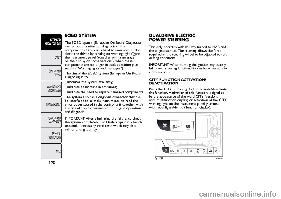
Press the CITY button fig. 121 to activate/deactivate
the function. Activation of this function is signalled
by the appearance of the word CITY (versions
with multifunction display) or activation of the CITY
warning light on the instrument panel (versions
with reconfigurable multifunction display).
fig. 121
F0Y0036
128GETTING TO
KNOW YOUR CAR
SAFETY
STARTING AND
DRIVING
WARNING LIGHTS
AND MESSAGES
IN AN EMERGENCY
SERVICING AND
MAINTENANCE
TECHNICAL
SPECIFICATIONS
INDEX