Page 89 of 156
 for up to")
Erase all channels before you begin programming. To erase the channels, place the ignition
switch into the ON/RUN position, then press and hold the two outside HomeLink® buttons
(I and III) for up to 20 seconds or until the red indicator flashes.
NOTE:
Erasing all channels should only be performed when programming HomeLink® for the first
time. Do not erase channels when programming additional buttons.
If you have any problems, or require assistance, please call toll-free 1-800-355-3515 or, on
the Internet at www.HomeLink.com for information or assistance.
Programming A Rolling Code
NOTE:
For programming Garage Door Openers that were manufactured after 1995. These Garage Door
Openers can be identified by the “LEARN” or “TRAIN” button located where the hanging
antenna is attached to the Garage Door Opener. It is NOT the button that is normally used to
open and close the door. The name and color of the button may vary by manufacturer.
1. Place the ignition switch into the ON/RUN position.
2. Place the hand-held transmitter 1 to 3 in (3 to 8 cm) away from the HomeLink® button youwish to program while keeping the HomeLink® indicator light in view.
3. Simultaneously press and hold both the HomeLink® button you want to program and the hand-held transmitter button.
4. Continue to hold both buttons and observe the indicator light. The HomeLink® indicator will flash slowly and then rapidly after HomeLink® has received the frequency signal
from the hand-held transmitter. Release both buttons after the indicator light changes
from slow to rapid.
5. At the garage door opener motor (in the garage), locate the “LEARN” or “TRAINING” button. This can usually be found where the hanging antenna wire is attached to the
garage door opener motor. Firmly press and release the “LEARN” or “TRAINING” button.
NOTE:
You have 30 seconds in which to initiate the next step after the LEARN button has been
pressed.
6. Return to the vehicle and press the programmed HomeLink® button twice (holding the button for two seconds each time). If the device is plugged in and activates, program-
ming is complete.
NOTE:
If the device does not activate, press the button a third time (for two seconds) to complete
the training.
7. To program the remaining two HomeLink® buttons, repeat each step for each remaining button. DO NOT erase the channels.
ELECTRONICS
87
Page 90 of 156

Programming A Non-Rolling Code
NOTE:
For programming Garage Door Openers manufactured before 1995.
1. Turn the ignition switch to the ON/RUN position.
2. Place the hand-held transmitter 1 to 3 inches (3 to 8 cm) away from the HomeLink®button you wish to program while keeping the HomeLink® indicator light in view.
3. Simultaneously press and hold both the HomeLink® button you want to program and the hand-held transmitter button.
4. Continue to hold both buttons and observe the indicator light. The HomeLink® indicator will flash slowly and then rapidly after HomeLink® has received the frequency signal
from the hand-held transmitter. Release both buttons after the indicator light changes
from slow to rapid.
5. Press and hold the programmed HomeLink® button and observe the indicator light. If the indicator light stays on constantly, programming is complete and the garage door (or
device) should activate when the HomeLink® button is pressed.
6. To program the two remaining HomeLink® buttons, repeat each step for each remaining button. DO NOT erase the channels.
Using HomeLink®
• To operate, press and release the programmed HomeLink® button. Activation will nowoccur for the programmed device (e.g., garage door opener, gate operator, security
system, entry door lock, home/office lighting, etc.,). The hand-held transmitter of the
device may also be used at any time.
WARNING!
• Your motorized door or gate will open and close while you are programming the
universal transceiver. Do not program the transceiver if people or pets are in the path
of the door or gate.
• Do not run your vehicle in a closed garage or confined area while programming the
transceiver. Exhaust gas from your vehicle contains Carbon Monoxide (CO) which is
odorless and colorless. Carbon Monoxide is poisonous when inhaled and can cause
you and others to be severely injured or killed.
ELECTRONICS
88
Page 91 of 156

POWER INVERTER
• There is a 115 Volt, 150 Watt power inverteroutlet located on the left rear trim panel
immediately behind the second row left
passenger seat. This outlet can power
cellular phones, electronics and other
low power devices requiring power up to
150 Watts.
• Press the switch located in the center of the instrument panel to turn the power to
the outlet on.
• Press the switch again to turn the power off.
• The status indicator of the AC power inverter indicates whether the inverter is producing AC power.
NOTE:
The power inverter is designed with built-in overload protection. If the power rating of
150 Watts is exceeded, the power inverter will automatically shut down. Once the electrical
device has been removed from the outlet, the inverter should automatically reset. If the
power rating exceeds approximately 170 Watts, the power inverter may have to be reset
manually. To reset the inverter manually, unplug the device and plug it in again. To avoid
overloading the circuit, check the power ratings on electrical devices prior to using the
inverter.
WARNING!
To Avoid Serious Injury or Death DO NOT:
• use a three-prong adaptor
• insert any objects into the receptacles
• touch with wet hands
Close the lid when not in use. If this outlet is mishandled, it may cause an electric shock
and failure.
ELECTRONICS
89
Page 92 of 156
 power outlets are lo-
cated on the lower instrument panel, below
the open storage bin. The driver-side power
outlet is controlled by the ignition switch
and the p")
POWER OUTLETS
•Two 12 Volt (13 Amp) power outlets are lo-
cated on the lower instrument panel, below
the open storage bin. The driver-side power
outlet is controlled by the ignition switch
and the passenger-side power outlet is
connected directly to the battery. The
driver-side power outlet will also operate a
conventional cigar lighter unit (if equipped
with an optional Smoker's Package).
• One outlet in the removable floor console (if equipped) shares a fuse with the lower
outlet in the instrument panel and is also
connected to the battery. Do not exceed a maximum power of 160 Watts (13 Amps)
shared between the lower panel outlet and the removable floor console outlet.
• On vehicles equipped with the Super Console the power outlets are located under the retractable cover. To access the power outlets push down on the cover and slide it toward
the instrument panel.
• The outlet in the rear quarter panel near the liftgate and the upper outlet in the instru- ment panel are both controlled by the ignition switch. Each of these outlets can support
160 Watts (13 Amps). Do not exceed 160 Watts (13 Amps) for each of these outlets.
ELECTRONICS
90
Page 93 of 156
NOTE:
• Do not exceed the maximum power of 160 Watts (13 Amps) at 12 Volts. If the 160 Watt(13 Amp) power rating is exceeded, the fuse protecting the system will need to be
replaced.
• Power outlets are designed for accessory plugs only. Do not insert any other object in the power outlet as this will damage the outlet and blow the fuse. Improper use of the power
outlet can cause damage not covered by your new vehicle warranty.
ELECTRONICS
91
Page 94 of 156

IN-FLOOR STORAGE — STOW'N GO®
Second Row Seat Storage Bins
• Storage bins are located in the floor in front of the second row seats that can be usedwhen the second row seat is in the upright position. Pull up on the storage bin latch to
open the cover. Slide the storage bin locking mechanism to the "Lock" position to allow
greater access to the storage bin.
Cargo Area Storage
• The liftgate sill plate has a raised line with the statement “Load To This Line”. This lineindicates how far rearward cargo can be placed without interfering with liftgate closing.
WARNING!
In a collision, serious injury could result if the seat storage bin covers are not properly
latched. Do not drive the vehicle with the storage bin covers open. Keep the storage bin
covers closed and latched while the vehicle is in motion. Do not use a storage bin latch
as a tie down.
ROOF LUGGAGE RACK
• The crossbars on your vehicle are deliv-ered stowed within the roof rack side rails.
When installed, the roof rack can hold a
maximum of 150 lbs (68 kg) of evenly
distributed weight.
Installing The Crossbars
•
To install the crossbars, completely loosen
the thumb screws at both ends and lift the
crossbar from its stowed position.
• Bend the pivot points at each end of the crossbar and slide the thumb screw down.
• Set the crossbars into position and tighten the thumb screws.
NOTE:
Make sure the directional arrow on the
crossbar aligns with the directional arrow on
the side rail.
• Refer to the Owner's Manual on the DVD for further details.
Crossbar
1 — Directional Arrow
2 — Pivot Point
3 — Thumb Screw
UTILITY
92
Page 95 of 156

Engine/
Transmission GCWR (Gross
Combined Wt. Rating) Frontal Area Max. GTW
(Gross Trailer Wt.) Max. Tongue Wt.
3.6L/Automatic 8,750 lbs
(3,969")
TRAILER TOWING WEIGHTS (MAXIMUM TRAILER WEIGHT
RATINGS)
Engine/
Transmission GCWR (Gross
Combined Wt. Rating) Frontal Area Max. GTW
(Gross Trailer Wt.) Max. Tongue Wt.
3.6L/Automatic 8,750 lbs
(3,969 kg) 40 sq ft
(3.72sqm) Up to 2 persons
& Luggage3,600 lbs
(1,633 kg) * 360 lbs (163 kg)
8,750 lbs
(3,969 kg) 40 sq ft
(3.72sqm) 3 to 5 persons &
Luggage
3,350 lbs
(1,519 kg) * 335 lbs (152 kg)
8,750 lbs
(3,969 kg) 40 sq ft
(3.72sqm) 6 to 7 persons &
Luggage
3,000 lbs
(1,360 kg) * 300 lbs (136 kg)
* For vehicles equipped with Fold-in-Floor seating, the Gross Trailer Weight must be reduced by 100 lbs (45 kg). Refer to local laws for maximum trailer towing speeds.
NOTE: The trailer tongue weight must be considered as part of the combined weight of occupants and cargo, and should never exceed the weight referenced on the Tire and Loading Information placard.
RECREATIONAL TOWING (BEHIND MOTORHOME, ETC.)
Towing Condition Wheels OFF the Ground All Models
Flat Tow NONE
NOT ALLOWED
Dolly Tow Front
OK
Rear NOT ALLOWED
On Trailer ALLOK
UTILITY
93
Page 96 of 156
Recreational Towing — All Models
• Recreational towing is allowed ONLY if the front wheels are OFF the ground. This may beaccomplished using a tow dolly or vehicle trailer. If using a tow dolly, follow this proce-
dure:
1. Properly secure the dolly to the tow vehicle, following the dolly manufacturer's instructions.
2. Drive the front wheels onto the tow dolly.
3. Firmly apply the parking brake. Place the transmission in PARK.
4. Properly secure the front wheels to the dolly, following the dolly manufacturer's instructions.
5. Release the parking brake.
CAUTION!
• DO NOT flat tow this vehicle. Damage to the drivetrain will result.
• Towing this vehicle in violation of the above requirements can cause severe trans- mission damage. Damage from improper towing is not covered under the New
Vehicle Limited Warranty.
UTILITY
94
 1
1 2
2 3
3 4
4 5
5 6
6 7
7 8
8 9
9 10
10 11
11 12
12 13
13 14
14 15
15 16
16 17
17 18
18 19
19 20
20 21
21 22
22 23
23 24
24 25
25 26
26 27
27 28
28 29
29 30
30 31
31 32
32 33
33 34
34 35
35 36
36 37
37 38
38 39
39 40
40 41
41 42
42 43
43 44
44 45
45 46
46 47
47 48
48 49
49 50
50 51
51 52
52 53
53 54
54 55
55 56
56 57
57 58
58 59
59 60
60 61
61 62
62 63
63 64
64 65
65 66
66 67
67 68
68 69
69 70
70 71
71 72
72 73
73 74
74 75
75 76
76 77
77 78
78 79
79 80
80 81
81 82
82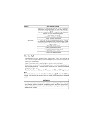 83
83 84
84 85
85 86
86 87
87 88
88 89
89 90
90 91
91 92
92 93
93 94
94 95
95 96
96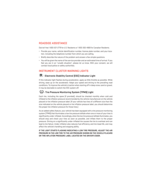 97
97 98
98 99
99 100
100 101
101 102
102 103
103 104
104 105
105 106
106 107
107 108
108 109
109 110
110 111
111 112
112 113
113 114
114 115
115 116
116 117
117 118
118 119
119 120
120 121
121 122
122 123
123 124
124 125
125 126
126 127
127 128
128 129
129 130
130 131
131 132
132 133
133 134
134 135
135 136
136 137
137 138
138 139
139 140
140 141
141 142
142 143
143 144
144 145
145 146
146 147
147 148
148 149
149 150
150 151
151 152
152 153
153 154
154 155
155 at 12 Volts. If the 160 Watt(13 Amp) power rating is exceeded, the fuse protecting the system will need to be
replaced.
• Power outle")
