Page 257 of 292

11. Deactivate the vehicle jack mode* in the
MMI:
! CARI function button> (C ar)* sys
tem s
control button > Servicing & chec ks
> Air susp. : jack mo de> Off .
The vehicle jack mode* switches off automati
cally at speeds above 6 mph (10 km/h).
A WARNING
Always read and follow all WARNINGS and
information
c:> .&. in Raising the vehicle on
page 257
and c::> page 259.
After changing a wheel
A wheel change is not complete without the
doing the following .
.. Always store the vehicle tool kit, the jack*
and the replaced tire in the luggage com
partment
c::> page 129.
.. As soon as possible, have the tighten ing
torqu es
on all wheel bolts checked with a
torque wrench . The correct tightening tor
que is 90 ft lb (120 Nm) .
.. Have the flat tire
re pl ace d as soon as poss i
ble.
@ Tips
- If you notice that th e whee l bolts are
corroded and difficult to turn wh ile
changing a t ire, they should be replaced
before you check the tighten ing torque .
- Drive at reduced speed unt il you have the
tightening torq ues checked .
- After changing a wheel, the tire pressure
i n a ll four tires must be checked/cor rect
ed and the tire pressure mon itoring indi
cator must be stored in the MM I
c::>page248 .
What do I do now ? 255
Wheels with wheel bolt caps
Applies to vehicles: with wheel bolts with caps
The caps must be removed first from the
wheel bolts before the bolts can be un
screwed .
Fig. 208 C hanging a whee l: removi ng the wheel bo lt
caps
Removing
.. Push the pla stic clip (provided with the veh i
cle too l kit) over the wheel bo lt cap until the
inner retainers on the clip align w ith the
edge of the cove r.
.,. Remove the cap with the
plas tic clip (ve hicle
too l kit)
c::> fig. 208 .
Refitting
.,. Place the caps over the whee l bolts and
push them back on.
The caps are to protect and keep the wheel bolts clean.
Loosening and tightening the wheel
bolts
The wheel bolts must be loosened before rais
ing the vehicle.
Fig. 209 Changing a wheel: loosening t he wheel bolts ..
Page 258 of 292

256 What do I do now?
Loosening
.,. Slide the wheel wrench onto the wheel bolt
as far as it will go.
.,. Take tight hold of the
end of the wrench
handle and turn the wheel bolts
counter
clockwise
about one single turn in the direc
t ion of arrow
c:;, fig. 209.
Tightening
.,. Slide the wheel wrench onto the wheel bolt
as far as it will go .
.,. Take tight hold of the
end of the wrench
hand le and turn each wheel bolt
clockwise
until it is seated.
_& WARNING
- Do not use force or hurry when changing
a wheel -you can cause the vehicle to slip
off the jack and cause serious personal injuries.
- Do not loosen the wheel bolts more than
one turn
before you raise the vehicle with
the jack. -You risk an injury.
@ Tips
- Never use the hexagonal socket in the
handle of the screwdriver to loosen or
tighten the wheel bolts.
- If a wheel bolt is very tight, you may find
it easier to loosen by carefully pushing
down on the end of the wheel bolt
wrench with
one foot only. As you do so,
hold on to the car to keep your balance
and take care not to slip.
Ra ising the vehicle
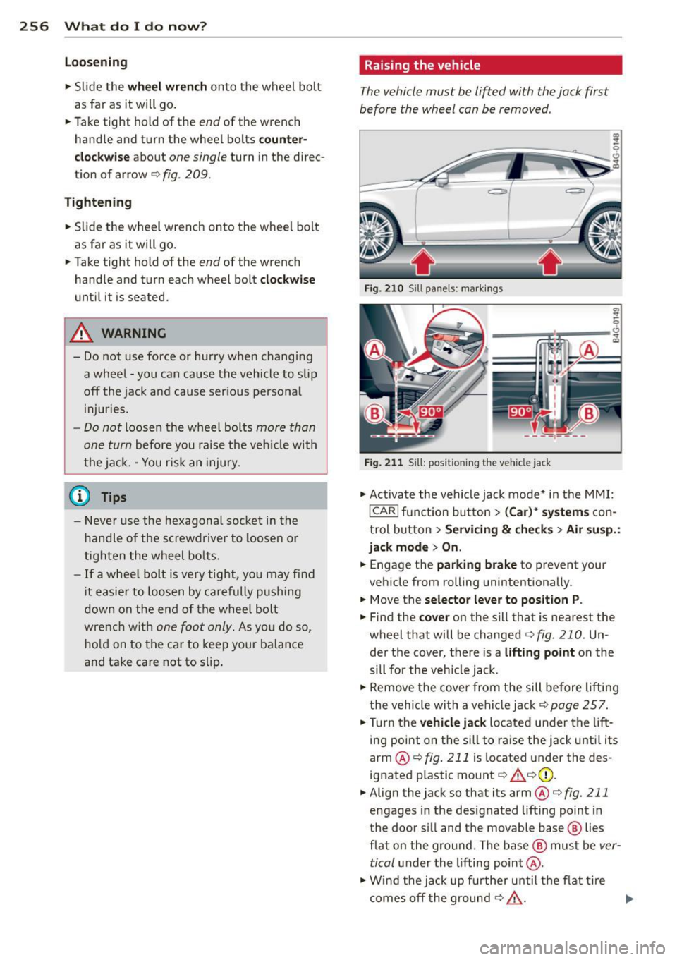
The vehicle must be lifted with the jack first
before the wheel can be removed .
Fig. 210 Sill pane ls : markings
; q
--~~~~~-~
Fig. 211 Sill: posit ioning the Ve hicle jack
.,. Activate the vehicle jack mode* in the MMI:
!CARI function button> (Car)* systems con
trol button>
Servicing & checks> Air susp.:
jack mode
> On.
.,. Engage the parking brake to prevent your
vehicle from rolling unintentionally.
.,. Move the
selector lever to position P .
.,. Find the cover on the sill that is nearest the
wheel that will be changed
c:;, fig. 210 . Un
der the cover, there is a
lifting point on the
sill for the vehicle jack .
.,. Remove the cover from the sill before lifting
the vehicle with a vehicle jack
c:;, page 257 .
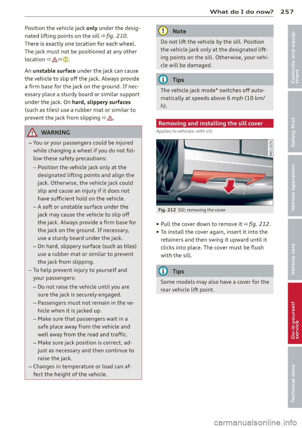
.,. Turn the vehicle jack located under the lift
ing point on the sill to raise the jack until its
arm @
c:;, fig. 211 is located under the des
ignated plastic mount
c:;, &c:;,(I) ,
.,. Align the jack so that its arm @ c:;, fig. 211
engages in the designated lifting point in
the door s ill and the movable base @ lies
flat on the ground . The base @ must be
ver
tical
under the lifting point @ .
.,. Wind the jack up further until the flat tire
comes off the ground
c:;, & . ..,.
Page 259 of 292

Position the vehicle jack o nl y under the desig
nated lifting points on the sill
¢ fig . 210.
There is exactly one location for each wheel.
The jack must not be positioned at any other
location¢ 8_¢Q) .
An
un sta bl e s urf a ce under the jack can cause
the vehicle to slip off the jack. Always provide
a firm base for the jack on the ground. If nec
essary place a sturdy board or s imilar support
u nder the jack . On
hard, slippery su rf ac es
(such as tiles) use a rubber mat or sim ila r to
prevent the jack from sli pping ¢&. .
A WARNING
-You or your passengers could be injured
wh ile chang ing a whee l if you do not fol
low these safety precautions:
- Position the vehicle jack only at the
des ignated lifting points and align the
jack . Otherwise, the vehicle jack could
slip and cause an injury if it does not
have sufficient ho ld on the vehi cle.
- A soft or unstab le surface under the
jack may cause the vehicle to slip off the jack. A lways provide a firm base for
the jack on the gro und. If necessary,
use a sturdy board under the jack.
- On ha rd, slippery surfa ce (such as tile s)
use a rubbe r mat o r similar to prevent
the jack from slipping.
- T o help prevent injury to yourself and
yo ur passenge rs:
- Do not raise the vehicle unti l you are
sure the jack is securely engaged.
- Passengers must not remain in the ve hicle when it is jacked up.
- Make sure that passengers wait in a
safe place away from the vehicle and
well away from the road and traffic .
- Make sure jack position is correct, ad just as necessary and then continue to ra ise the jack.
- Changes in temperature or load can af
fect the height of the vehicle.
What do I d o now ? 257
(D Note
Do not lift the vehicle by the sil l. Position
the veh icle jack only at the designated lift
i ng po ints on the sill. Otherwise, your vehi
cle will be damaged.
{!) Tips
The vehicle jack mode* switches off auto
matically at speeds above 6 mp h (10 km/
h).
Removing and installing the sill cover
App lies to vehicles: with sill
Fi g. 212 Sill: remov ing the cove r
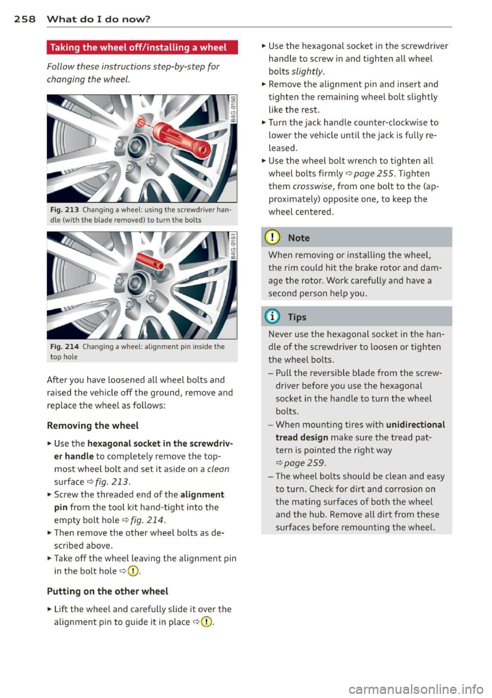
... Pull the cover down to remove it ~fig. 212.
... To insta ll the cover again, insert it into the
retainers and then swing it upward until it
clicks into p lace. The cover must be flush
w ith the sill.
(D Tips
Some models may also have a cover for the
rear vehicle lift point.
Page 260 of 292

2 58 What do I do now ?
Taking the wheel off/installing a wheel
Follow these instructions step-by-step for
changing the wheel.
Fig. 213 Changing a whee l: u sing the screwdriver han
dle (w ith the blade removed } to turn t he bolts
Fig . 214 C hanging a w hee l: al ignm en t pi n inside the
top hole
Afte r you have loosened a ll wheel bolts and
raised the vehicle off the ground, remove and
replace the wheel as follows:
Removing the wheel
.. Use the hexagonal socket in the screwdriv
er handle
to comp letely remove the top
most wheel bolt and set it aside on a
clean
surface c:> fig. 213 .
.. Screw the threaded end of the alignment
pin
from the tool kit hand -tight into the
empty bolt hole
c:> fig. 214.
.. The n remove the other wheel bo lts as de
scribed above .
.. Take off the wheel leaving the alignment pin
in the bolt hole
c:> (D .
Putting on the other wheel
.. Lift the wheel and carefully slide it over the
alignment pin to guide it in place
c:>(D.
.. Use the hexagonal socket in the screwdriver
handle to screw in and tighten all whee l
bolts
slightly.
.. Remove the alignment pin and insert and
tighten the remaining wheel bolt slightly like the rest .
.. Turn the jack handle counter-clockwise to
lower the vehicle until the jack is fully re
leased .
.. Use the wheel bolt wrench to tighten all
wheel bolts fir m ly
c:> page 255 . Tighten
them
crosswise, from one bolt to the (ap
proximately) opposite one, to keep the
wheel centered.
(D Note
When remov ing or installing the wheel,
the rim cou ld hit the brake rotor and dam
age the rotor. Work carefu lly and have a
second person help you.
(D Tips
Never use the hexagonal socket in the han
d le of the screwdriver to loosen or tighten
the wheel bolts.
- Pull the reversible blade from the screw
driver before you use the hexagonal
socket in the handle to turn the wheel
bolts.
- When mounting tires w ith
unidirectional
tread design
make sure the tread pat
tern is pointed the right way
c:>page25 9.
-The wheel bolts should be clean and easy
to turn . Check for dirt and corrosion on
the mating surfaces of both the wheel
and the hub. Remove all dirt from these
surfaces before remounting the wheel.
Page 261 of 292

Tires with unidirectional tread design
Tires with unidirectional tread design must be
mounted with their tread pattern pointed in the right direction .
Using a replacement tire with a tre ad
patte rn intend ed for us e in a specific
directi on
When us ing a replacement t ire with a tread
pattern intended for use in a specific direc
tion, please note the fo llowing :
- T he direction of rotation is marked by an ar
row on the side of the tire .
-If the replacement tire has to be installed in
t h e incorrect d irection, use the rep lacement
t ire only temporarily since the t ire will not
be able to achieve i ts optimum performance
characteristics with regard to aquap laning,
noise and wear .
- We recommend that you pay particular at
tention to this fact during wet weather and
that you adjust your speed to match road conditions .
- Replace the flat tire with a new one and
have it installed on you r veh icle as soon as
poss ible to restore the handling advantages
of a unid irect ional tire.
Notes on wheel changing
P lease read the information ¢ page 239, New
tires and replacing tires and wheels
i f you are
go ing to use a replacement tire w hich is dif
fe rent from the tires on your vehicle.
After you change a ti re :
- Chec k the tir e p ress ure on the rep lacement
t ire immed ia tel y aft er in stall ation.
- Ha ve the wheel bolt tight ening torque
checked w ith a to rqu e wrench as soon as
possible by your auth oriz ed Aud i dealer o r
a qu alifi ed s erv ice station .
- With steel and allo y wheel rims , the wheel
bol ts are correctl y tightened at a to rque of
9 0 ft lb (1 20 Nm ).
- If y ou no tice th at the whee l bolts are cor
roded and d ifficult to tu rn whil e cha nging
What do I do now? 259
a tire , th ey s hould be repl aced before you
c heck the tightening torq ue.
- Repl ac e th e flat ti re with a new on e and
ha ve it in sta lled on you r veh icle as s oon a s
po ssible. Remount the whee l cove r.
Until then , dri ve with extr a care and at r e
du ced sp ee ds.
A WARNING
-=
- If you are going to equip your vehicle
with tires or rims which differ from those
which were factory installed, then be sure to read the information ¢
page 239,
New tires and replacing tires and
wheels .
-Always make sure the damaged wheel or
even a flat tire and the jack and tool kit
are properly secured in the luggage com
partment and are not loose in the pas
senger compartment .
- In an accident or sudden maneuver they
co uld fly forwa rd , injuring anyone in the
veh icle.
- Always sto re damaged wheel, jack and
too ls securely in the luggage compa rt
men t. Othe rwise , in an accident or s ud
den maneuver they co uld f ly forward ,
causing injury to passengers in the vehi
cle.
([) Note
Do not use commercially avai lab le tire
sea lants . O therwise, the e lectr ica l compo
nents of the tire pressure monitoring sys
tem will no longer work properly and the
sensor for the tire pressure mon itor ing
system will have to be rep laced by quali
fied workshop. •
•
Page 262 of 292

260 Fuses and bulbs
Fuses and bulbs
Fuses
Replacing fuses
Fuses that have blown will have metal strips
that have burned through.
Fig. 215 Driver side of the cockpit: fuse panel cover
The fuses are located at the front left and
right of the cockpit and behind the trim on
the right side of the luggage compartment.
• Switch the ign ition and the affected electri
cal equ ipment off.
• Check the following table to see which fuse
belongs to the consumer.
• Remove the cover ¢
fig. 215 or¢ page 211,
Opening the side trim.
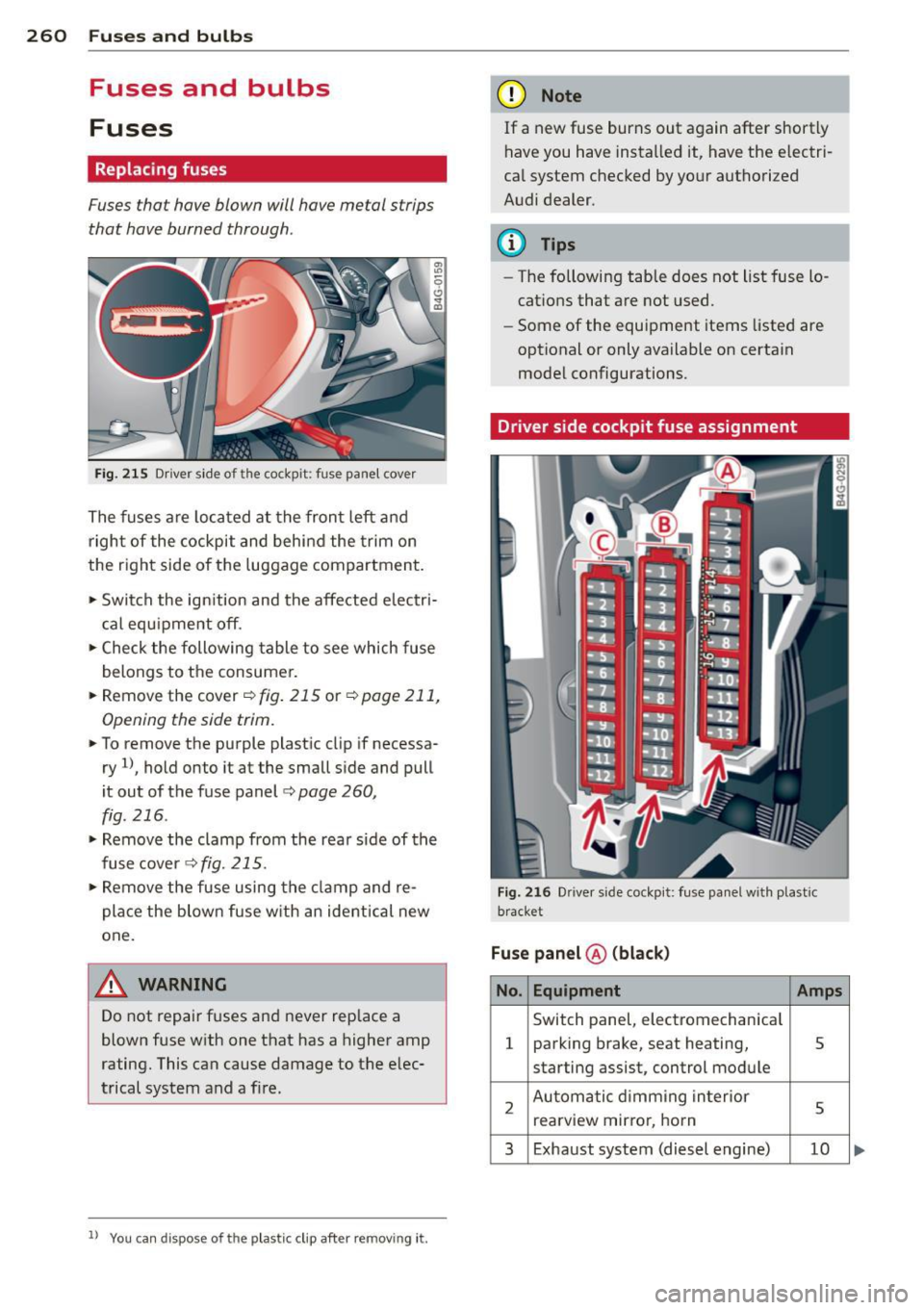
• To remove the purple plastic clip if necessa
ry
ll, hold onto it at the small side and pull
it out of the fuse panel
c:> page 260,
fig. 216 .
• Remove the clamp from the rear s ide of the
fusecover <>fig.
215.
• Remove the fuse using the clamp and re
pla ce the blown fuse w ith an ident ical new
one.
A WARNING
Do not repair fuses and never replace a
blown fuse with one that has a higher amp
rating. This can cause damage to the elec
trical system and a fire.
ll You can dis pose of the plastic clip after re moving it.
(D Note
If a new fuse burns out again after shortly
have you have installed it, have the electri
cal system checked by your authorized
Audi dealer.
(D Tips
-The following table does not list fuse lo
cations that are not used.
- Some of the equipment items listed are
optional or only available on certain
model configurations.
Driver side cockpit fuse assignment
Fig. 216 Dr ive r side cockpit: fuse panel with plastic
bracket
Fuse panel ® (black)
No. Equipment Amps
Switch panel, electromechanical
1 parking brake, seat heating, 5
starting assist, control module
2 Automatic dimming interior
5 rearview mirro r, horn
3 Exhaust system (diesel engine) 10
Page 263 of 292

No. Equ ipment Amps
4 Suspension control system sen-s sor
s
E
lectronic Stabilization Cont rol
s (ESC) module
6 Climate control
5
7 Adaptive cruise control 10
8
Airbag control module, front
5
passenger's seat sensor system
9 Gateway 5
Homelink (garage doo r opener),
10 night vis ion system cont ro l 5
module
11 Image
processing (active lane
10
ass ist, adaptive cruise control)
12 Dynamic steering 5
13 Terminal 15 in
the instrument
15
panel
14 Terminal 15
in the luggage com-
partment 30
15 Terminal 15
(engine)
15
16 Starter 40
Fu se pa nel ® (b rown )
No . Equipment Amps
1 Gateway
5
2 C limate control 10
3 E
lectronic Stabili zation Contro l
10
(ESC) module
4 Fron
t door (driver 's side)
30
s
Power seat adjustment (driver's
7,5
seat)
6 Dynam
ic steering
35
7 Sunroof 20
8
Rear door control module (driv-
15
er 's side)
9 Lumbar support (
Front passen-
s ger seat)
10 Tire pressure
monitoring system
5
11 Su
nroof, rear spoi ler (Sportba ck)
20
12 Driver
door control module
15
Fuse s and bulb s 261
Fuse pan el© (r e d )
No . Equipment
2 Fuel pump
3 Brake light sensor/brake pedal
sensor system
AdBlue control module (Diesel)/
4 Engine acoust ics
5 Left rear door cont rol modu le
6 Power seat adjustment
(pas-
senge r's seat)
7 Horn
8 Windshield wiper motor
9 Light/rain sensor, heater
for vid-
eo camera in windscreen
10 L umba r support (driver seat)
1 1 Front
passenger door control
modu le
12 Right rea r door cont rol modu le
Front passenger side cockpit fuse
assignment Amp
s
25
5/5
5/7,S 30
7,5 15
30
s
5
15
15
F ig . 217 Front passenger side cockpit: fuse pa nel w it h
plast ic brac ket
Fuse panel @ (bla ck)
No . Equipment Amps
1 Head-up
Display
5
2 MMI Display 5
3 CO/DVD changer
5
4 MMI unit/drives 7,5
5 Chip
card reader (not in all coun-
5
tries)
6 Instrument
cluster
5
7 Steering column switch module 5 ...
Page 264 of 292

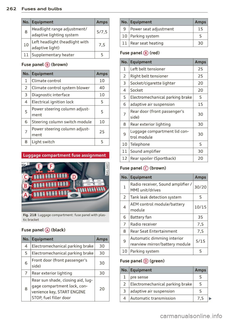
262 Fuses and bulb s
No. Equ ipment Amps
8
Headlight range adjustment/
5/7,S
adaptive lighting system
10 Left headlight
(headlight with
7,5
adaptive light)
11 Supplementary
heater
s
Fuse p ane l@ (b ro w n)
No . Equipment Amps
1 Climate control
10
2 Climate control system blower 40
3 Diagnostic interface
10
4 E lectrical ignition lock
s
s
Power steering column adjust-
s ment
6 Steering column switch module
10
7 Power steering column adjust-
ment
25
8 Light
switch
s
Luggage compartment fuse assignment
Fig. 218 Luggage compartment: fuse panel with plas
tic bracket
Fuse p anel @ (b la ck )
No. Equipment Amps
4 E lectromechanical parking brake 30
s Electromechanical parking brake
30
6 Front door
(front passenger's
30
s ide)
7 Rear exter ior lighting
30
Rear sun shade, closing aid, lug-
8 gage compartment lock, con-
20
venience key, START ENGINE
STOP, fuel filler door
No. Equipment Amps
9 Power seat adjustment
15
10 Parking system
s
11 Rear seat
heating
30
Fuse pan el@ (r e d )
No . Equipment Amps
l Left belt tensioner
25
2 Right belt tensioner 25
3 Socket/cigarette
lighter
20
4 Socket 20
s Electromechanical parking brake s
6 adaptive ai r suspension 15
7 Rear door
(front passenger's
30
side)
8 Rear exterior lighting 30
9 Luggage compartment
lid con-
30
t rol modu le
10 Telephone
s
11 Sound amplifier 30
12 Rear
spoiler (Sportback)
20
Fuse pan el© (brown)
No . Equipment Amps
1 Radio
receiver, Sound amplifier/
30/20
MMI unit/drives
2 Tank leak detection system
s
4 AEM
control module/battery
10/15
module
6 Battery fan 35
7 Rad
io receiver 7,S
8 Rear Seat Entertainment 7,5
9 Automatic d
imming interior
5/15
rearview mirror/battery module
10 Parking system
s
Fuse pan el@ (gre en)
No . Equipment Amps
1 pre sense s
2 Electromechanical parking brake s
3 adaptive
air suspension 5
4 Automatic transmission 7,5