Page 25 of 292

Instrument s and warning /indicator lights 23
Driver information
display
Overview
Fig. 4 Driver info rmation system in the instrument
cluster
Fig . 5 Display: example of the informat ion line
The driver information system contains infor
mation
@ that is displayed on tabs ®
c::> fig. 4. The following content is possible de
pending on vehicle equipment:
®
®
Tab Content
1 Vehicle functions :
On-boa rd computer c::> page 24
Effic iency program* c::> page 25
Digital speedometer
Cruise control*
c::> page 79
Adaptive cru ise control and braking
guard *
c::> page 81
Audi active lane assist* c::>page 90
Boost, shifting and engine oil tern-
perature indicators
c::> page 28
Lap t imer
c::> page 29
Display darkened ®
®
Tab Content
2 Indicator lights and messages
Warn
ing when a door, the hood or
the rea r lid is not closed
Service interval dis play
c::> page 2 7
Speed warning system
c::> page 79
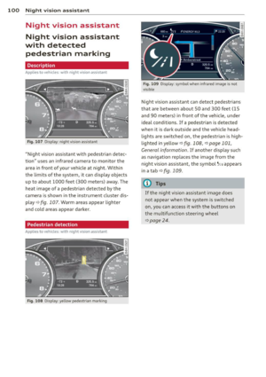
3 Night vision assistant* c::> page 100
4 Audio/video
5 Telephone*
6 Navigation*
The second and th ird tabs are only v isible if at
least one indicator light or message is shown
or if that system is sw itched on.
The status line © is located in the bottom
part of the disp lay
c::> fig. 4. It displays the ex
terior temperat ure, time, selector lever posi
tion, trip odometer and odometer.
For some vehicle functions, you can access the
trip information from the temporary memory
c::> page 24 in the line © c::> fig. 5.
A WARNING
-
- Never rely exclusively on the outside
temperature display to determine if a
road surface is icy or not. Keep in mind
that road surfaces, especially bridges
and overpasses, could be ice covered and
slippe ry even at an outside temperature
above 41 °F
(+5 °().
-Always remember, even if the "snow
flake" symbol (ice warning) does not ap
pear in the d isplay, black ice could be on
the road.
-Always reduce your speed and drive with
special care in cold weather cond itions
when the chance of encountering icy
road surfaces increases.
(D Tips
- At temperatures below 14 °F (+ 5 °C) a
snowf lake symbol appears ahead of the
t emperature display.
It is intended to re-
mind the driver to pay special attention .,._
Page 26 of 292

24 Instruments and warning /indicator lights
to ice on the road ¢ & . If the vehi cle is
stationary, o r if you are dr iving at a very
l ow speed, the tempe rat ure shown in the
display might be slightly higher t han the
actua l o utside temperature. This is
ca used by the heat being rad iated from
t h e eng ine.
- You can se lect the un its used for temper
atu re, speed a nd other measurements in
the MMI.
- Fo r informat ion on the a udio/video and
nav iga tion* functions, refer to the sepa
r ate MMI owner's manual.
Operation
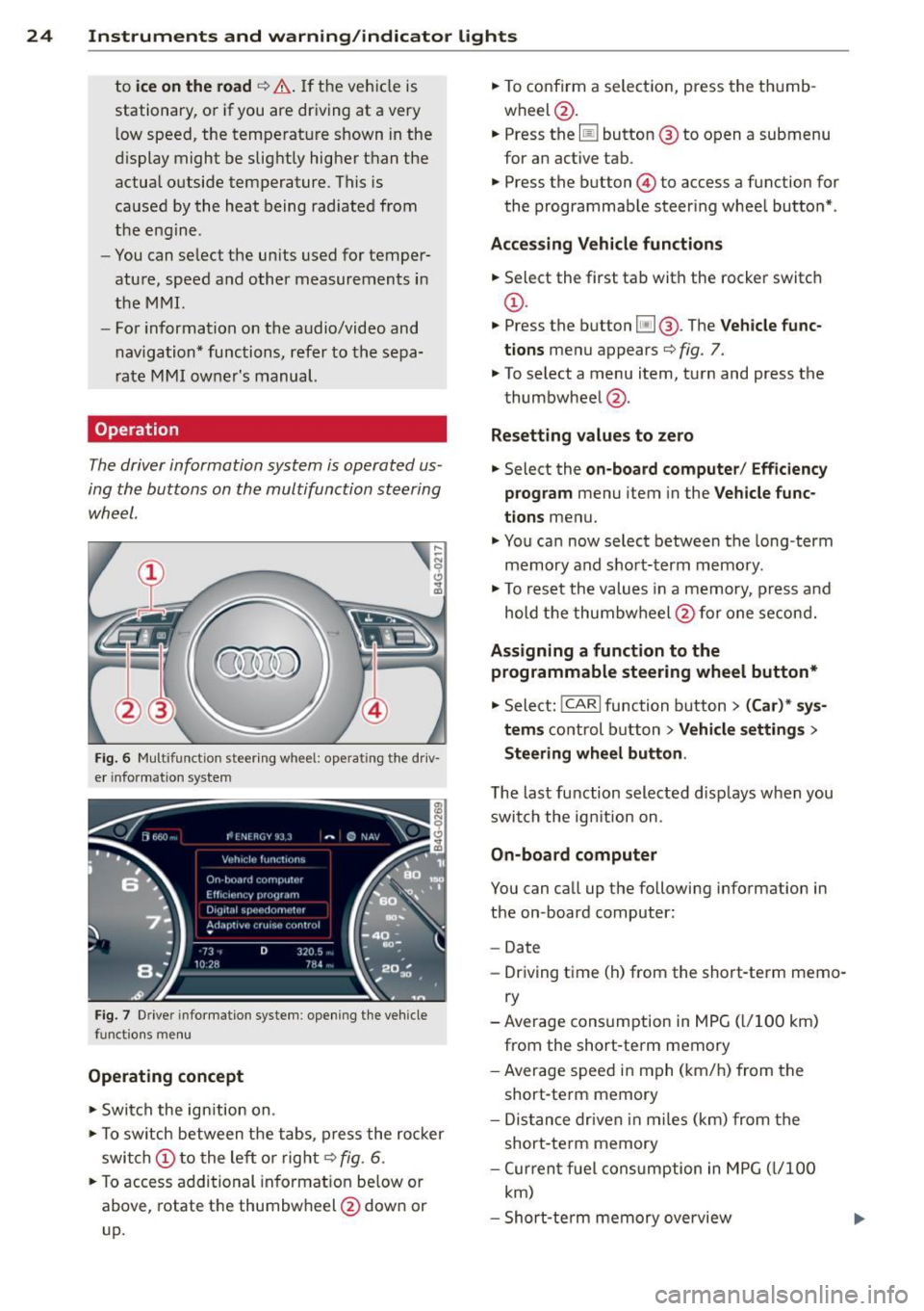
The driver information system is operated us
ing the buttons on the multifunction steering
wheel.
,... ~ N 0 Cl
"' m
Fig. 6 M ultifunction steer ing wheel: operating"the driv
e r in fo rm atio n system
Fi g. 7 Driver infor mat ion syste m: opening t he ve hicle
functio ns me nu
Operating concept
.. Swi tch the ign ition on.
.. To switch between the t abs, press the ro cker
swi tch
(D to the le ft or r ight¢ fig. 6 .
.. To access additional in format io n be low or
above, rotate t he thumbw heel @dow n or
up. ..
To confirm a selec tion, press the th umb
wheel @.
.. Press the
[jJ button @ to o pen a submenu
for an active tab .
.. Press the button@ to access a function for
the programmab le steer ing whee l butto n*.
Acces sing Vehicle functions
.. Select the first ta b with the rocker switc h
(D.
.. Press t he b utton [jj @. The Vehicle func
tions
menu appears¢ fig. 7.
.. To select a menu item, turn and press the
t humbwheel @.
Resett ing values to ze ro
.. Select the on-board computer / Efficiency
program
menu item in the Vehicle func
tions
menu .
.. You ca n now select between the long-term
memory and s ho rt -t erm memory.
.. To res et the valu es in a me mory, press a nd
hold t he thumbw heel @for one se con d.
Assigning a function to the
programmable steering wheel button*
.. Select: !CARI function button> (Car) * sys-
tem s
control button > Vehicle settings >
Steering wheel button .
The last function selected disp lays w hen you
swi tch the ig nition on.
On-board computer
You can ca ll up the followi ng info rmation in
the on-board computer:
- Date
- Dr iving time (h) from the short-term memo-
ry
-Average consumption in MPG ( l/1 00 km)
from the short-te rm memory
- Average spee d in m ph ( km/ h) fr om the
short-te rm memory
- Dis tance driven i n m iles (km) from the
short -te rm memory
- Cur ren t fu el con sumption in MPG ( l/1 00
km)
- Short-te rm memory overview
Page 27 of 292

Instrument s and warning /indicator lights 25
- Long-term memory overview
The short-term memo ry co llects driving infor
mat ion from the time the ignition is switched
on un til it is switched off. If you continue dr iv
ing within two hours after switching the igni
tion off, the new values are included when cal
culating the current trip information.
Unlike the short-te rm memory, the long-term
memory is not erased automatically. You can
select the time period for evaluating trip in
formation yourself.
F or some veh icle functions, you can access the
trip information from the temporary memory
in the line
(D r=;, page 23, fig. 5.
The cu rrent fuel consumpt ion can be dis
p layed using a bar
r=;, page 26, fig. 10. The
average consumption (mpg) stored in the
short-term memory is also displayed. Electri
cal energy can be stored in the battery when
the vehicle is coasting or driving downhill (re
cuperation) . The bar will move toward
t:3 .
Efficiency prog ram
The efficiency program can help you to use
less fuel.
It evaluates driving information in
reference to fuel consumption and shows oth
er equipment influencing consumption as well
as shift recommendations.
r=;, page 25. Fuel
economy messages
r=;, page 25 provide tips
for efficient driving . The effic iency program
uses distance and consumption data from tr ip
computer
1.
To display the efficiency program, call up Ve
hicle functions and select the menu option
Efficiency program . If the data are deleted in
the efficiency program, those values are also
reset in trip computer .
(j) Tips
-All stored va lues will be lost if the veh i
cle battery is disconnected.
- Fuel consumptions (average and cur
rent), range and speed are displayed in
metric units on Canadian models.
Other equipment
Fig . 8 On -board computer : other equipment
Requirement: The efficiency program must be
displayed
r=;, page 25 .
.,. Turn the thumbwheel unti l the other equip-
ment appears in the display .
Other equipment that is currently affecting
fuel consumption is listed in the efficiency
program. The display shows up to three other
items of equipment @. The equipment using
the most fuel is listed first. If more than three
items using fuel are switched on, the equip
ment that is currently using the most fuel is
displayed .
A scale @also shows the current total con
sumption of all other equipment.
Fuel economy messages
Fig. 9 Disp lay: example of a fuel econo my m essa ge
Fuel economy messages are displayed when
fuel consumption is increased by certain con
ditions. If you follow these fuel economy mes
sages, you can reduce your vehicle's consump
t ion of fuel. The messages appear automat i
cally and are only displayed in the efficiency
program . The fue l economy messages turn off
automat ical ly after a certa in period of time . .,.
Page 28 of 292

26 Instruments and warning /indicator lights
• To turn an economy message off immediate
l y after it appears, press any b utton on the
mult ifunction steer ing whee l.
(D Tips
-Once you have t urne d a fue l eco nomy
message off , it will only appear again af
ter you t urn the ignition on aga in.
- The fuel eco nomy messages are not dis
played in every instance, but rathe r in in
terva ls over a per iod of time.
Cylinder on demand System
App lies to vehicles: with 4.0 TFSI engine
Fig. 10 In strument cluster : fu el con sumpt io n
To save f uel, the eng ine automat ica lly t urns
four cylinders on or off, depending on the
amo unt of power needed . This action is not
fe lt by the passengers.
Displaying cylinder mode
Requ irement : th e on-bo ard computer is dis
p layed
q page 24 .
• Turn the thumbwhee l until the current fue l
co nsu mp tion d isplay is shown in the in st ru
ment cluster. I f the green bar i s di splayed ,
yo u are driving in 4-cylinder mo de.
Basic requirements for 4 -cylinder mode
4-cy linder d rive mode is used automatically if
certain basi c req uiremen ts are fu lfi lled . T hese
i n cl ude:
-A low powe r outp ut requi rement .
- Driving i n third gear or higher.
- Engine speed between 960 and 3,500 RP M.
- A warm engine .
Odometer
Fig. 11 Inst ru m ent clus ter : Odo meter an d reset b ut
t o n
T he odometer shows you how ma ny m iles
( kil ome te rs ) you have drive n. You can swi tch
t h e d is pl ay from miles to ki lomete rs and v ice
versa via t he MMI.
Upper odometer
The trip odometer shows the distanc e driven
s in ce it was last reset .
It can be u sed to meas
u re s ho rt dist ances . T he last digit indica tes
1/10 o f a mile (10 0 me ters) .
You can res et the trip odometer to zero by
pressing the Reset bu tton
@J .
Lower odometer
The lower odomete r shows the tota l number
of miles (kilometers) dr iven .
Malfunct ion message
If there is a malfunct ion in the instrument
cluster ,
DEF will appear in the trip odometer
display area . Contact your author ized Audi
dealer to have the problem corrected .
Time and date display
Fig. 12 Instrume nt cluster: clock a nd da te
Page 29 of 292

Instrument s and warning /indicator lights 2 7
You can set the time and the date display in
the MMI. Refer to the MMI owner's manua l
for instructions.
When you open the drive r's door, the date and
time appear in the inst rument cluste r display
for 30 seconds .
Service interval display
Th e service int erval display r eminds you when
your next service is due.
F ig . 13 Inst ru m en t cl uste r: Service inte rva l d is pl ay
The schedule for the next oil change or inspec
tion is calculated automatically and displayed
according ly . The display works in two stages :
Serv ice reminder
30 days before the next service is due, a serv ice reminder appears in the display when yo u
switch the ignition on
c::;, fig. 13 .
Afte r abo ut 5 seconds the display sw itches
back to normal. The d istance and time re
maining are updated each time the ignition is
switched on un til the date due for service is
reac hed .
Service due
W hen the due date for service is reached, the
message
Service due! appears in the instru
ment cluster immediately after you switch the
ignit io n on . Additionally, a warn ing tone
sounds. After about 5 seconds the display
switches back to normal.
Calli ng up the service schedules
If or when an oil change or inspection is due,
can be shown in the MMI d isplay by select ing
the service interva l disp lay in the car menu . Se
lect the
ICAR I function button > (Car )* sys
tems
control button > Ser vicing & checks >
Service interval d isp lays. In new ve hicles, the
schedule can only be called up after approxi
mately 500 km.
Resetting the service interval display
Your a uthorized Audi dea le r will reset the cor
responding service sc hedule after pe rforming
the appropriate service on your veh icle . You
also have the possib ility to reset the oil
c h ange schedule after hav ing performed an
o il change according to Aud i specifications.
Se lect the
ICA RI function button> (Car )* sys
tems
control button > S ervicing & checks >
Servi ce Interval s > Reset oil change interval.
(D Note
If you discon nect t he batt ery te rminals, no
ca lculatio ns can b e ma de fo r the s ervic e
i nte rva l di sp lay dur ing th is time and n o
se rv ice re minder will ap pea r. R emem ber
that o bserving t he prop er servi ce inte rva ls
i s vitally important to extending the life of
your vehicle, pa rtic ularly the engine, and
maintain ing its val ue. Eve n if the mileage
driven is low, the max imum per iod of one
year from one service t o the next must not
b e exceeded .
(D Tips
- Do not reset the display betwee n oil
changes, otherwise the disp lay will be in
co rrect.
- The info rmation in t he Service Reminder
remains st ored eve n w hen t he ve hicle
bat tery is disco nnec ted .
Page 30 of 292

28 Instruments and warning/indicator lights
Head-up Display
Applies to vehicles: with Head-up Display
Fig. 14 Example: indicators in the Head-up Disp lay
Fig. 15 Instrument panel: knob fo r the Head -up Dis
p lay
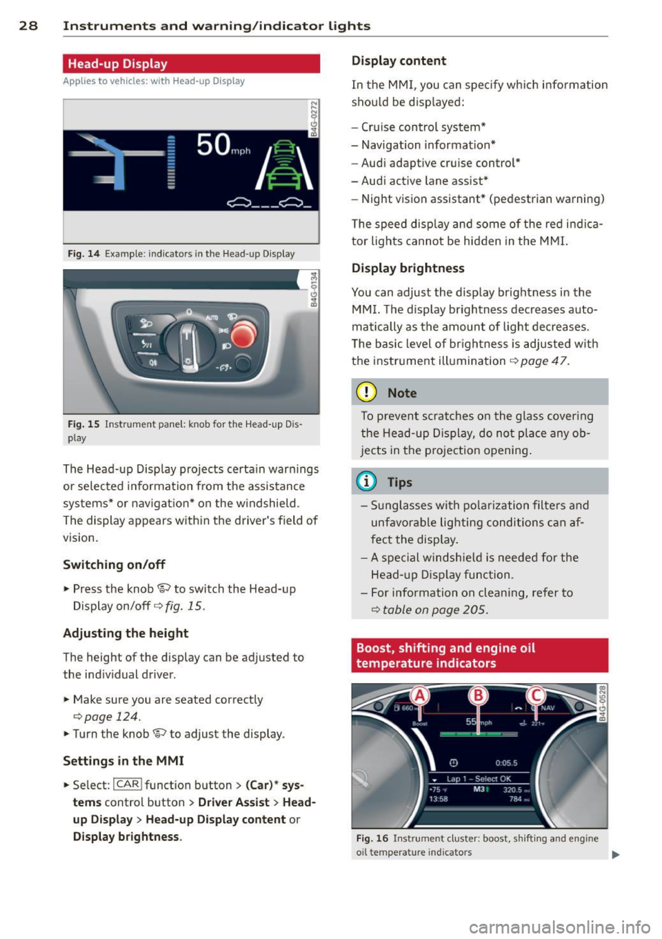
The Head-up Display projects certain warnings
or selected information from the assistance
systems* or navigation* on the windshield .
The display appears with in the driver's field of
vision.
Switching on/off
,.. Press the knob~ to switch the Head-up
Display on/off
c::> fig. 15.
Adjusting the height
The height of the display can be adjusted to
the indiv idual driver .
,.. Make sure you are seated correctly
c:> page 124.
,. Turn the knob ~ to adjust the display .
Settings in the MMI
,.. Se lect : I CAR ! funct ion button > (Car)* sys
tems
control button > Driver Assist > Head
up Display
> Head-up Display content or
Display brightness . Display content
In
the MMI, you can spec ify which information
shou ld be disp layed:
- Cruise control system*
- Navigation information*
- Audi adaptive cruise control*
-Audi active lane assist*
- Night vision assistant* (pedestrian warning)
The speed disp lay and some of the red indica
tor lights cannot be hidden in the MMI.
Display brightness
You can adjust the display brightness in the
MMI. The d isp lay brightness decreases auto
matically as the amount of light decreases.
T he basic level of brigh tness is adjusted with
the instrument illumination
c::> page 47.
(D Note
To prevent scratches on the glass cover ing
the Head-up Display, do not place any ob
jects in the projection opening.
(D Tips
-Sunglasses with polarization filters and
unfavorable lighting conditions can af
fect the disp lay.
- A spe cial windshie ld is needed for the
Head- up Display function .
- For info rmat ion on clean ing, refer to
Q table on page 205.
Boost, shifting and engine oil
temperature indicators
Fig. 16 Instrumen t cluster: boost, shi fti ng and eng ine
oil te mp erat ure in dicators .,..
Page 31 of 292

Instrument s and warning /indicator lights 29
.. Turn the menu thumbwheel on the steering
whee l until
Lap time r appears in the instru
ment cluster disp lay .
@ Boost pressure indicator
The current engine load (meaning the current
boost p ressure) is indicated by a bar.
@ Shifting indicator
The shifting i ndicator is only visib le when
shifting gears with the selector lever in tip
tronic mode
c> page 108. Green LEDs turn on
as the engine RPMs increase. The LEDS flash
red at speeds near the RPM lim it.
I n vehicles with a head-up d isplay, the shifting
indicator is shown in the head-up display in
stead of the instr ument cluster. The head-up
display must be switched on in orde r to do
this
c> page 28.
© Engine oil temperature indicator
I f the engine oil temperature is below 60 °(,
the G¥J symbol followed by three hyphens" --
-" and the °C unit is shown.
The engine has reached its operating temper
ature when the engine o il temperature is be
tween 60
· c and 120 °C under normal driv ing
conditions. The eng ine oi l temperature may
be h igher if there is heavy engine load and
high temperatures outside. This is not a cause
for concern as long as the. ~
page 17 or
l!I c> page 17 warning light in the display
does not flash.
Lap timer
Introduction
You can record and eva luate lap times with
the lap timer in the display
c> page 29,
fig. 17 . The time is measured in minutes, sec
onds and 1/10 seconds . The hours are also
shown when the lap time exceeds 60 minutes.
The maximum individual measurement is
99
hours . A maximum of 50 laps may be record
ed .
A WARNING
Please devote your full attention to driv
ing . As the driver, you have complete re
sponsib ility for safety in traffic. Only use
the functions in such a way that you always
maintain complete control over your vehi
cle in all traffic situations.
(D Tips
When the lap timer stopwatch is running,
you can call up the on-board computer in
formation.
Calling up the lap timer and timing
Fig. 17 Display: Lap t imer
Calling up the lap timer
.. Turn the thumbwheel until the lap timer ap-
pears.
Timing laps
.. To start t iming, press the thumbwhee l.
.. To stop t iming for this lap, press the thumb
wheel again . This also starts timing the next
round. The previous timing always moves
one line up. The lap number that corre
sponds to the timing is displayed in front of
the individual tim ings .
Displaying intermediate time and paus ing
timing
.,. To display an intermediate time, press the
thumbwheel. The timing continues to run in
the backg round.
.. To pause timing, press the thumbwheel.
.. To continue timing, press the thumbwheel
again.
Page 32 of 292

30 Instruments and warning/indicator lights
If timing is paused, you can continue it late r
even if you sw itch the ignition off .
Evaluating times and continuing or
resetting timing
You can evaluate the fastest, slowest and
average lap times.
Fig. 18 Dis play : lap time eva luat ion
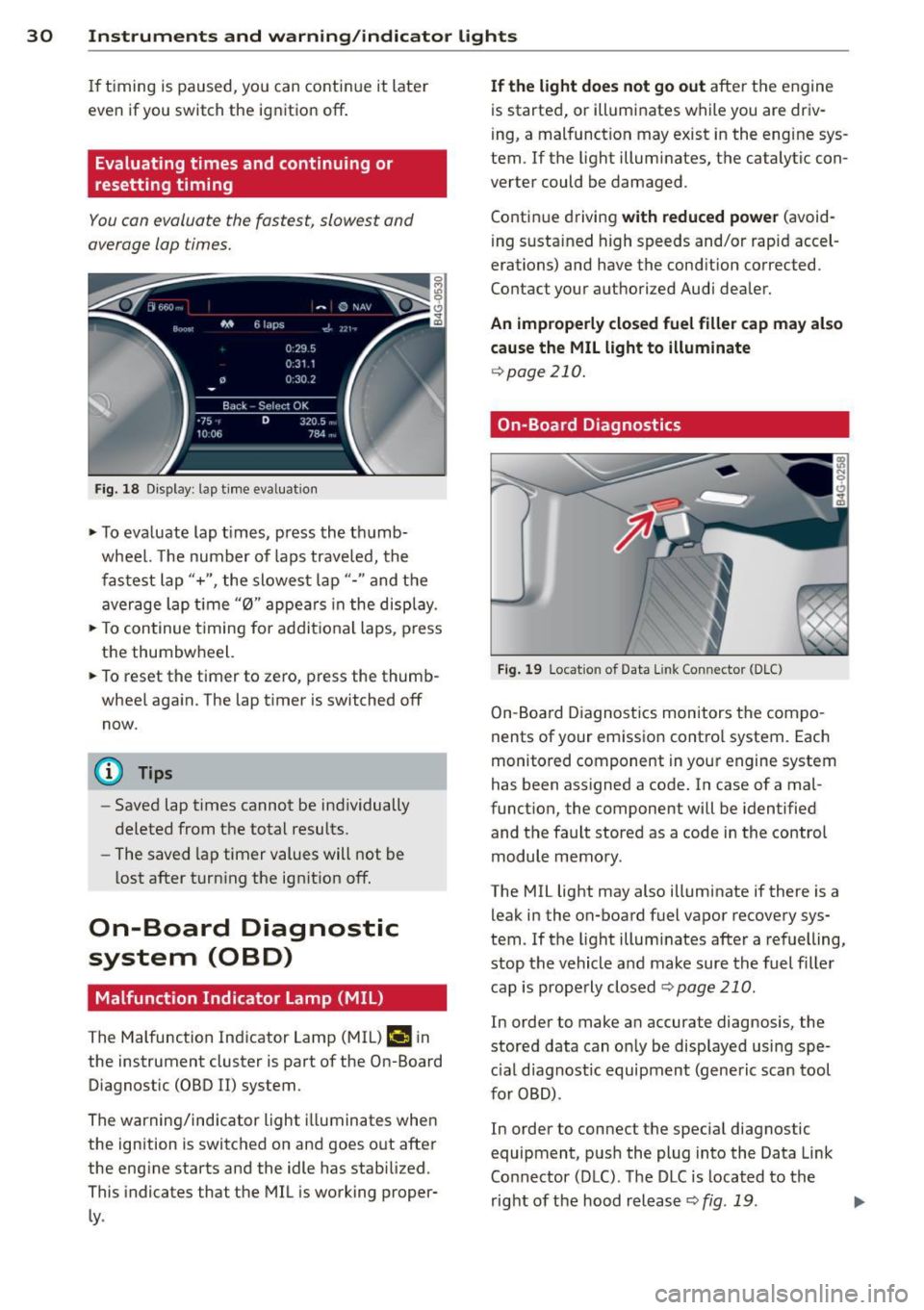
.,. To evaluate lap times, press the thumb
wheel. The number of laps traveled, the
fastest lap"+", the slowest lap"- " and the
average lap t ime "0" appears in the display .
.,. To continue t iming for addit ional laps , press
the thumbwheel.
.,. To reset the timer to zero, press the thumb
wheel again. The lap timer is switched off now.
@ Tips
- Saved lap times cannot be individually
deleted from the total results.
- The saved lap timer values will not be
lost after turning the ignit ion off.
On-Board Diagnostic
system (OBD)
Malfunction Indicator Lamp (MIL)
The Malfunction Indicator Lamp (MIL) ¢4 in
the instrument cluster is part of the On-Board Diagnostic (OBD
II) system.
The warning/indicator light illuminates when
the ignition is switched on and goes out after
the engine starts and the idle has stabilized .
This indicates that the MIL is working proper
ly .
If the light does not go out after the engine
is started, or illuminates while you are driv
ing, a malfunction may exist in the eng ine sys
tem . If the light illuminates, the catalytic con
verter could be damaged .
Continue driving
with reduced power (avoid
ing sustained high speeds and/or rapid accel
erations) and have the condition corrected.
Contact your authorized Audi dealer.
An improperly closed fuel filler cap may also
cause the MIL light to illuminate
¢page 210.
On-Board Diagnostics
Fig. 19 Locat io n of Data Link Co nnector (D LC)
On-Board Diagnostics monitors the compo
nents of your emission control system . Each
monitored component in your engine system
has been assigned a code. In case of a mal
function, the component will be identified
and the fault stored as a code in the control
module memory.
The MIL light may also illuminate if there is a leak in the on-board fuel vapor recovery sys
tem. If the light illuminates after a refuelling,
stop the vehicle and make sure the fuel filler
cap is properly closed
Q page 210 .
In order to make an accurate diagnosis, the
stored data can only be displayed using spe
c ial d iagnostic equipment (generic scan tool
for OBD) .
In order to connect the special diagnostic
equipment, push the plug into the Data Link
Connector (DLC). The DLC is located to the
right of the hood release
Q fig . 19 . liJJ,