Page 552 of 796

11-158910-05
3) Audio Setting
If you press the "SETUP" button, the text "EQ" appears in the display. When you turn the volume
control dial, the texts appear in the following order: "EQ" ↔ "TONE" ↔ "BT".
When the specific text appears, press the ENTER button to set the entry. However, if no choice has
been made within 5 seconds, the Setting mode is quit automatically.
Press SET button to enter the Setting mode. “EQ”, “TONE” and “BT” appear on the display.
Rotate TUNE dial to select the “EQ” menu, then press ENTER button.
Rotate TUNE dial to select the desired EQ style, then press ENTER button. 1.
2.
3.Selecting the Equalizer style ▶
If no key input is made for 5 seconds, the current status is saved and the Setting mode is quit.
*If no key input is made for 5 seconds, the current status is saved and the Setting mode is quit.
*By rotating the TUNE dial, you can select one of the following EQ Styles.
EQ OFF ↔ POP ↔ ROCK ↔ COUNTRY ↔ VOICE↔ JAZZ ↔ CLASSIC ↔ .... -
By rotating the TUNE dial, you can select one of the following Tone Control items.
BASS ↔ MIDDLE ↔ TREBLE ↔ BALANCE ↔FADER ↔ PREVIOUS ↔ .... - Press SET button to enter the Setting mode. “EQ”, “TONE” and “BT” a
ppear on the display
Rotate TUNE dial to select the “TONE” menu, then press ENTER button.
Rotate TUNE dial to select the desired Tone control item, then press ENTER button. 1.
2.
3.Setting the sound (TONE) ▶
Rotate TUNE dial to adjust the value of the level or balance, then press ENTER button. 4.
BASS: adjust the bass sound level (-7 to +7).
MIDDLE: adjust the treble sound level (-7 to +7).
TREBLE: adjust the treble sound level (-7 to +7).
BALANCE: adjust the sound balance between the right and left speakers (LEFT15 to RIGHT15).
FADER: adjust the sound fade between the front and rear speakers (FRONT15 to REAR15).
PREVIOUS: return to the TONE menu. -
-
-
-
-
-
Page 604 of 796

05-53240-01
Operation ▶
Description Mode Conditions
Driving mode 2H 2 Wheel drive
(rear wheel)Rear-wheel drive mode. This is used under normal
or high-speed driving conditions on public roads or
highways.
4H 4 Wheel drive
(high speed)This is used under sandy, muddy or snow-covered
road conditions
4 L 4 Wheel drive
(low speed)This is used for maximum traction.
When cornering with low speed in 4WD condition,
there could be tire dragging, some
mechanical shocks and resistances in vehicle’s
drive train. These are normal conditions due to
internal resistance in the drive train when the
4WD system is properly working
Mode change2H ↔
4H 2 Wheel drive
↔4 Wheel driveShifting is possible while driving at the speed of
70 km/h or less
2H, 4H
↔ 4L 2 Wheel drive,
4 Wheel drive
(high speed)
↔4 Wheel drive
(low speed)
To make the mode change easily, stop the
vehicle on level ground and turn the mode
switch to the desired position and move the
shift lever to "N"-"R"-"N" while depressing the
brake pedal. For Automatic Transmission:
Stop the vehicle on level ground and move the
gear selector lever into the “N”
position. Turn
the switch to the desired position. -
For Manual Transmission:
Stop the vehicle on level ground and move the
gear selector lever into the “N” position.
Then turn the switch to the desired position
while depressing the clutch pedal. -
Page 624 of 796

07-94411-01
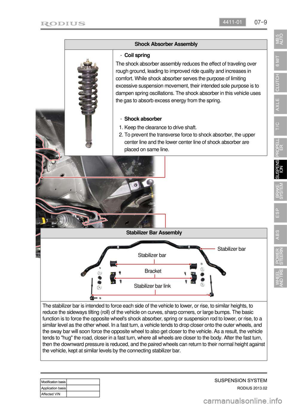
Shock Absorber Assembly
Stabilizer Bar Assembly
The stabilizer bar is intended to force each side of the vehicle to lower, or rise, to similar heights, to
reduce the sideways tilting (roll) of the vehicle on curves, sharp corners, or large bumps. The basic
function is to force the opposite wheel's shock absorber, spring or suspension rod to lower, or rise, to a
similar level as the other wheel. In a fast turn, a vehicle tends to drop closer onto the outer wheels, and
the sway bar will soon force the opposite wheel to also get closer to the vehicle. As a result, the vehicle
tends to "hug" the road, closer in a fast turn, where all wheels are closer to the body. After the fast turn,
then the downward pressure is reduced, and the paired wheels can return to their normal height against
the vehicle, kept at similar levels by the connecting stabilizer bar.
Stabilizer bar
Stabilizer bar
Bracket
Stabilizer bar link
Coil spring -
The shock absorber assembly reduces the effect of traveling over
rough ground, leading to improved ride quality and increases in
comfort. While shock absorber serves the purpose of limiting
excessive suspension movement, their intended sole purpose is to
dampen spring oscillations. The shock absorber in this vehicle uses
the gas to absorb excess energy from the spring.
Shock absorber -
Keep the clearance to drive shaft.
To prevent the transverse force to shock absorber, the upper
center line and the lower center line of shock absorber are
placed on same line. 1.
2.
Page 627 of 796

07-12
3. WHEEL ALIGNMENT
Wheel alignment (adjustment of Camber, Caster and Toe) is part of standard automobile maintenance
that consists of adjusting the angles of the wheels so that they are set to the specification. The purpose
of these adjustments is to reduce tire wear, and to ensure that vehicle travel is straight and true (without
"pulling" to one side). Alignment angles can also be altered beyond the specifications to obtain a specific
handling characteristic.
When viewed from the top, the distance between the tire centers is smaller in the front than in
the rear. ▶
Side slip protection
Parallel front wheels rotation (straight ahead driving is ensured by toe-in to prevent the wheels from tilting
outwards by the camber while driving)
Prevention of uneven (outward) tire wear Prevention of toe-out from wearing of steering linkage -
-
-
1) Toe-in
The difference of measured distances between the front ends of the tires (A) and the rear ends of the
tires (B) along the same axle when viewed the wheels from the top.
Toe-inFront0.˚±0.10˚
Rear0.48˚±0.15˚
Necessity for Wheel Alignment ▶
Wheel alignment consists of adjusting the angles of the wheels so that they are perpendicular to the
ground and parallel to each other. The purpose of these adjustments is maximum tire life and a vehicle
that tracks straight and true when driving along a straight and level road.
The symptoms of a vehicle that is out of alignment are:
Uneven or rapid tire wear
Pulling or drifting away from a straight line
Wandering on a straight level road
Spokes of the steering wheel off to one side while driving on a straight and level road.
Page 628 of 796

07-134411-01
2) Camber
The angle between the center line of the tire and the vertical line when viewed from the front of the
vehicle
CamberFront-0.12˚±0.50˚
Rear-1.20˚±0.50˚
Zero camber: When the tire center line is perpendicular to the ground level ▶
Disadvantages:The axle is easy to be bent or deviated in the negative camber than in the
positive camber when load is applied on the axle.
Difficult to control due to wide load area. -
- Advantages:Better traction force due to wide load area (applicable for off-road vehicle)
Better corner driving when the vehicle makes turn as the cornering force -
- Negative camber ▶Disadvantages:Cornering force decreases as the positive camber increases when the vehicle
makes turn.
The hub bearing is worn unevenly if camber is excessive. -
- Advantages:The axle is not bent when it is loaded.
The force required to operate the steering wheel is reduced due to smaller
contact area (or load area) of the tire.
Restoring force of the steering wheel is gained (when turning the steering wheel,
the tire circles and the force to lift the frame is applied. In this case, the shock
absorber contracts and the restoration force is applied to the steering wheel.) -
-
- Positive camber: Top of the tire is tilted outward ▶
Page 629 of 796

07-14
3) Caster
The angle between the vertical line and king pin, which fixes the steering knuckle and front axle,
(steering column which connects the top and bottom ball joints in the independent axle type) when
viewed the tires from the side.
CasterFront4.80˚±0.50˚
Rear -
Disadvantages:Impact from the road is transferred to the steering wheel (steering wheel turns)
Poor straightness -
- Advantages:Directional force to go straight (following control)
Restoring force of the wheel (restored to the straight ahead direction)
Prevention of wheel shimmy (wheels wobble left and right) -
-
-
Negative caster: ▶Top of the king pin is tilted forward from the vertical line of the wheel center
when viewed the tires from the side Positive caster: ▶
With considering the height difference between the wheel centers of the front and rear
wheels. (Under standard condition that the vehicle is on a level ground) Caster: ▶
Advantages:Smaller turning radius -Top of the king pin is tilted backward from the vertical line of the wheel center
when viewed the tires from the side
Page 630 of 796
08-34850-03
Brake oil Grade DOT 4
Service interval Replace every 2 years
1. SPECIFICATIONS
Description Specification
Front brake Type Ventilated disc
Rear brake Type Ventilated disc
Master cylinder Type Step feed bore tandem, double cylinder
Brake booster Type Tandem type (integrated level sensor)
Operating type Foot operated type
Page 691 of 796

11-94610-00
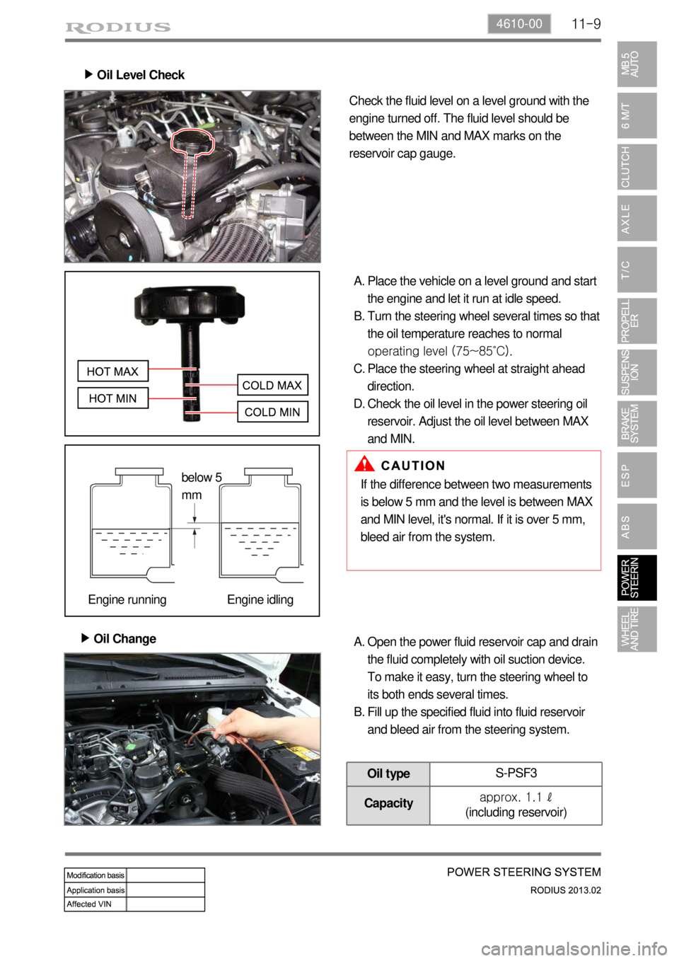
Oil Level Check ▶
Check the fluid level on a level ground with the
engine turned off. The fluid level should be
between the MIN and MAX marks on the
reservoir cap gauge.
Place the vehicle on a level ground and start
the engine and let it run at idle speed.
Turn the steering wheel several times so that
the oil temperature reaches to normal
operating level (75~85˚C).
Place the steering wheel at straight ahead
direction.
Check the oil level in the power steering oil
reservoir. Adjust the oil level between MAX
and MIN. A.
B.
C.
D.
Oil Change ▶
If the difference between two measurements
is below 5 mm and the level is between MAX
and MIN level, it's normal. If it is over 5 mm,
bleed air from the system.
Open the power fluid reservoir cap and drain
the fluid completely with oil suction device.
To make it easy, turn the steering wheel to
its both ends several times.
Fill up the specified fluid into fluid reservoir
and bleed air from the steering system. A.
B.
Oil typeS-PSF3
Capacityapprox. 1.1 ℓ
(including reservoir)
below 5
mm
Engine running Engine idling