2013 SSANGYONG TURISMO level
[x] Cancel search: levelPage 291 of 796

10-4
1. OVERVIEW
The pre-heating system for D20DTR engine has the glow plug to the cylinder head (combustion
chamber), and improves the cold start performance and reduces the emission level.
The pre-heating resistor (air heater) is used to heat the intake air.
This enables the diesel fuel to be ignited in low temperature condition.
The ECU receives the information such as, engine rpm, coolant temperature, engine torque, etc.,
through CAN communication during pre-heating process; and the pre-heating control unit controls the
pre-heating, heating during cranking and post-heating by the PWM control.
Glow plug
Engine ECU (D20DTR)Glow indicator
Glow plug control unit
(GCU)
Page 311 of 796

13-4
1. SYSTEM DESCRIPTION
1) Overview
The EGR (Electric-Exhaust Gas Recirculation) valve reduces the NOx emission level by recirculating
some of the exhaust gas to the intake system.
To meet Euro-V regulation, the capacity and response rate of E-EGR valve in D20DTR engine have
been greatly improved. The EGR cooler with high capacity reduces the Nox, and the bypass valve
reduces the CO and HC due to EGR gas before warming up.
Also, the engine ECU adjusts the E-EGR opening by using the air mass signal through HFM sensor. If
the exhaust gas gets into the intake manifold when the EGR valve is open, the amount of fresh air
through HFM sensor should be decresed.
Benefits of E-EGR valve ▶
Improved accuracy and response through electric control
Feedback function (Potentiometer)
Preventing chattering of EGR valve and improved durability
Self-cleaning function -
-
-
-
Page 315 of 796
14-32412-02
1. CAUTIONS
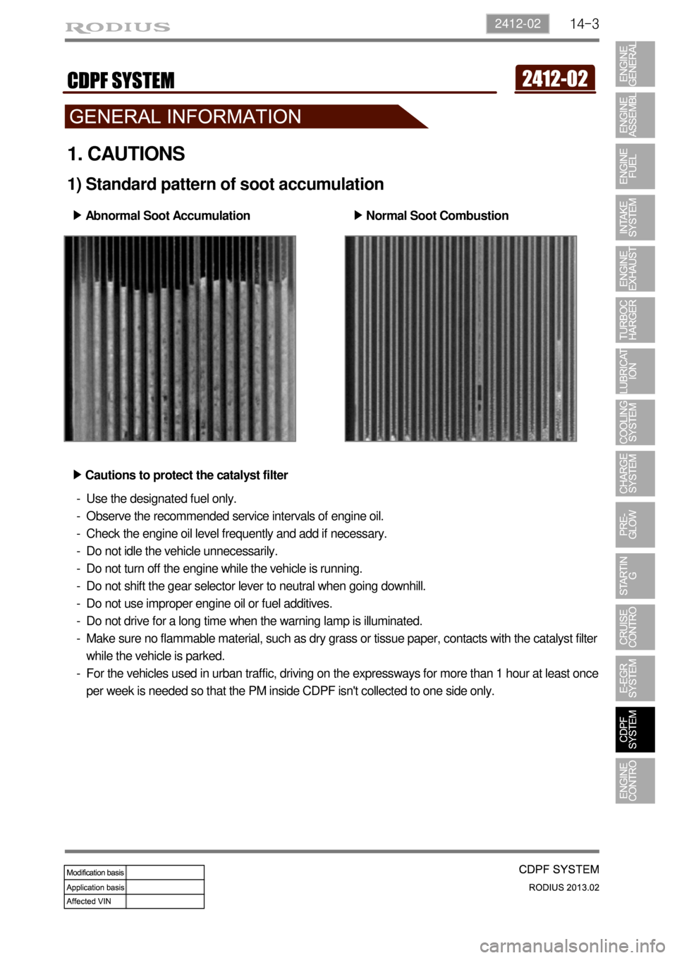
1) Standard pattern of soot accumulation
Abnormal Soot Accumulation ▶
Normal Soot Combustion ▶
Cautions to protect the catalyst filter ▶
Use the designated fuel only.
Observe the recommended service intervals of engine oil.
Check the engine oil level frequently and add if necessary.
Do not idle the vehicle unnecessarily.
Do not turn off the engine while the vehicle is running.
Do not shift the gear selector lever to neutral when going downhill.
Do not use improper engine oil or fuel additives.
Do not drive for a long time when the warning lamp is illuminated.
Make sure no flammable material, such as dry grass or tissue paper, contacts with the catalyst filter
while the vehicle is parked.
For the vehicles used in urban traffic, driving on the expressways for more than 1 hour at least once
per week is needed so that the PM inside CDPF isn't collected to one side only. -
-
-
-
-
-
-
-
-
-
Page 339 of 796
15-110000-00
2) ECU Control
(1) Function
a. ECU Function
ECU receives and analyzes signals from various sensors and then modifies those signals into
permissible voltage levels and analyzes to control respective actuators.
ECU microprocessor calculates injection period and injection timing proper for engine piston speed
and crankshaft angle based on input data and stored specific map to control the engine power and
emission gas.
Output signal of the ECU microprocessor drives pressure control valve to control the rail pressure and
activates injector solenoid valve to control the fuel injection period and injection timing; so controls
various actuators in response to engine changes. Auxiliary function of ECU has adopted to reduce
emission gas, improve fuel economy and enhance safety, comforts and conveniences. For example,
there are EGR, booster pressure control, autocruise (export only) and immobilizer and adopted CAN
communication to exchange data among electrical systems (automatic T/M and brake system) in the
vehicle fluently. And Scanner can be used to diagnose vehicle status and defectives.
Operating temperature range of ECU is normally -40 to +85°C and protected from factors like
oil, water and electromagnetism and there should be no mechanical shocks.
To control the fuel volume precisely under repeated injections, high current should be applied instantly
so there is injector drive circuit in the ECU to generate necessary current during injector drive stages.
Current control circuit divides current applying time (injection time) into full-in-current-phase and hold-
current-phase and then the injectors should work very correctly under every working condition.
b. Control Function
Controls by operating stages
To make optimum combustion under every operating stage, ECU should calculate proper injection
volume in each stage by considering various factors.
Starting injection volume control
During initial starting, injecting fuel volume will be calculated by function of temperature and engine
cranking speed. Starting injection continues from when the ignition switch is turned to ignition
position to till the engine reaches to allowable minimum speed.
Driving mode control
If the vehicle runs normally, fuel injection volume will be calculated by accelerator pedal travel and
engine rpm and the drive map will be used to match the drivers inputs with optimum engine power. -
-
-
Page 340 of 796
15-12
(2) Fuel injection control
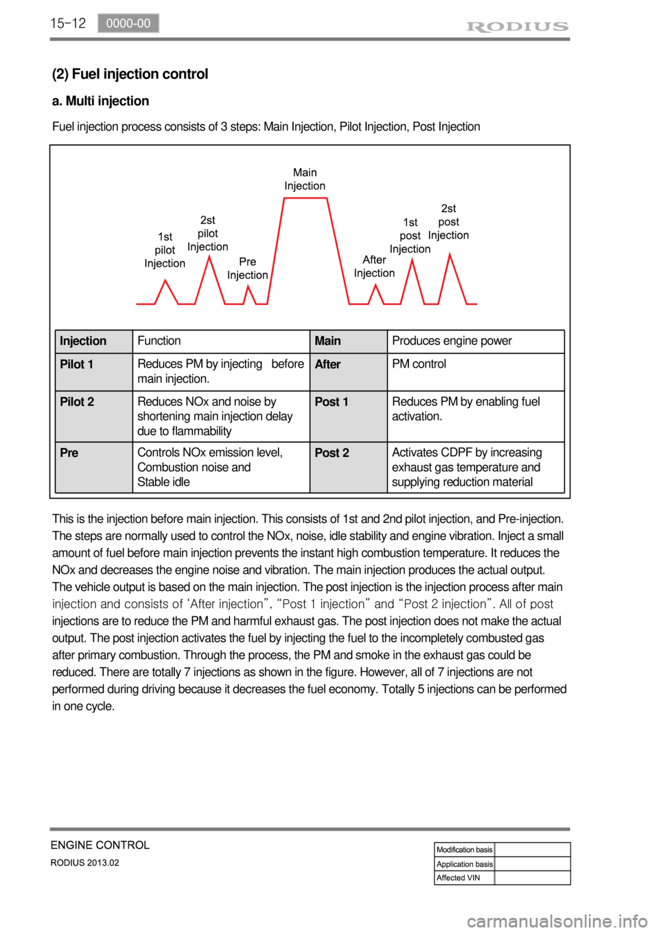
a. Multi injection
Fuel injection process consists of 3 steps: Main Injection, Pilot Injection, Post Injection
This is the injection before main injection. This consists of 1st and 2nd pilot injection, and Pre-injection.
The steps are normally used to control the NOx, noise, idle stability and engine vibration. Inject a small
amount of fuel before main injection prevents the instant high combustion temperature. It reduces the
NOx and decreases the engine noise and vibration. The main injection produces the actual output.
The vehicle output is based on the main injection. The post injection is the injection process after main
injection and consists of ‘After injection”, “Post 1 injection” and “Post 2 injection”. All of post
injections are to reduce the PM and harmful exhaust gas. The post injection does not make the actual
output. The post injection activates the fuel by injecting the fuel to the incompletely combusted gas
after primary combustion. Through the process, the PM and smoke in the exhaust gas could be
reduced. There are totally 7 injections as shown in the figure. However, all of 7 injections are not
performed during driving because it decreases the fuel economy. Totally 5 injections can be performed
in one cycle.
InjectionFunction
MainProduces engine power
Pilot 1Reduces PM by injecting before
main injection.AfterPM control
Pilot 2Reduces NOx and noise by
shortening main injection delay
due to flammability Post 1Reduces PM by enabling fuel
activation.
PreControls NOx emission level,
Combustion noise and
Stable idle Post 2
Activates CDPF by increasing
exhaust gas temperature and
supplying reduction material
Page 350 of 796
15-22
(7) Knocking Control
A. Resetting the pilot injection
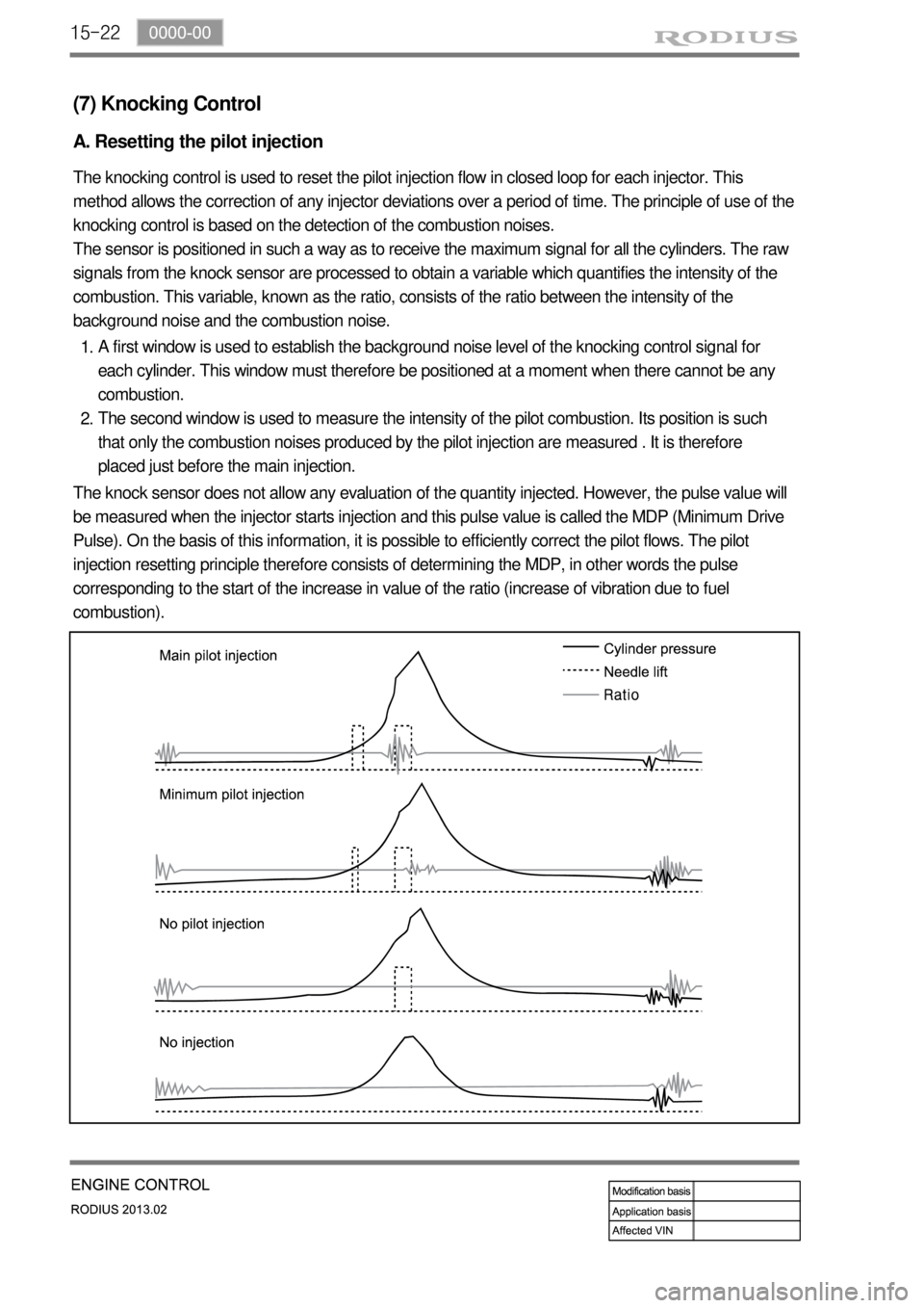
The knocking control is used to reset the pilot injection flow in closed loop for each injector. This
method allows the correction of any injector deviations over a period of time. The principle of use of the
knocking control is based on the detection of the combustion noises.
The sensor is positioned in such a way as to receive the maximum signal for all the cylinders. The raw
signals from the knock sensor are processed to obtain a variable which quantifies the intensity of the
combustion. This variable, known as the ratio, consists of the ratio between the intensity of the
background noise and the combustion noise.
A first window is used to establish the background noise level of the knocking control signal for
each cylinder. This window must therefore be positioned at a moment when there cannot be any
combustion.
The second window is used to measure the intensity of the pilot combustion. Its position is such
that only the combustion noises produced by the pilot injection are measured . It is therefore
placed just before the main injection. 1.
2.
The knock sensor does not allow any evaluation of the quantity injected. However, the pulse value will
be measured when the injector starts injection and this pulse value is called the MDP (Minimum Drive
Pulse). On the basis of this information, it is possible to efficiently correct the pilot flows. The pilot
injection resetting principle therefore consists of determining the MDP, in other words the pulse
corresponding to the start of the increase in value of the ratio (increase of vibration due to fuel
combustion).
Page 356 of 796

15-28
Electric throttle
bodyAccelerator
pedal
moduleD20DTR
ECU
(9) EGR control
A. Overview
The EGR (Electric-Exhaust Gas Recirculation) valve reduces the NOx emission level by recirculating
some of the exhaust gas to the intake system.
To meet Euro-V regulation, the capacity and response rate of E-EGR valve in D20DTR engine have
been greatly improved. The EGR cooler with high capacity reduces the Nox, and the bypass valve
reduces the CO and HC due to EGR gas before warming up.
Also, the engine ECU adjusts the E-EGR opening by using the air mass signal through HFM sensor. If
the exhaust gas gets into the intake manifold when the EGR valve is open, the amount of fresh air
through HFM sensor should be decresed.
B. Components
E-EGR cooler
Coolant
temperature
sensorOxygen sensor
HFM (intake
air
temperature)
Crankshaft
position
sensorE-EGR valve
T-MAP
sensor
Page 358 of 796
15-30
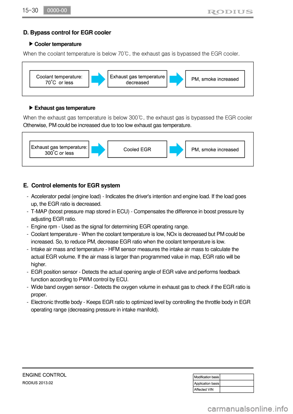
D. Bypass control for EGR cooler
Cooler temperature ▶
When the coolant temperature is below 70℃, the exhaust gas is bypassed the EGR cooler.
Exhaust gas temperature ▶
When the exhaust gas tem
perature is below 300℃, the exhaust gas is bypassed the EGR cooler
Otherwise, PM could be increased due to too low exhaust gas temperature.
E. Control elements for EGR system
Accelerator pedal (engine load) - Indicates the driver's intention and engine load. If the load goes
up, the EGR ratio is decreased.
T-MAP (boost pressure map stored in ECU) - Compensates the difference in boost pressure by
adjusting EGR ratio.
Engine rpm - Used as the signal for determining EGR operating range.
Coolant temperature - When the coolant temperature is low, NOx is decreased but PM could be
increased. So, to reduce PM, decrease EGR ratio when the coolant temperature is low.
Intake air mass and temperature - HFM sensor measures the intake air mass to calculate the
actual EGR volume. If the air mass is larger than programmed value in map, EGR ratio will be
higher.
EGR position sensor - Detects the actual opening angle of EGR valve and performs feedback
function according to PWM control by ECU.
Wide band oxygen sensor - Detects the oxygen volume in exhaust gas to check if the EGR ratio is
proper.
Electronic throttle body - Keeps EGR ratio to optimized level by controlling the throttle body in EGR
operating range (decreasing pressure in intake manifold). -
-
-
-
-
-
-
-