Page 319 of 796

14-72412-02
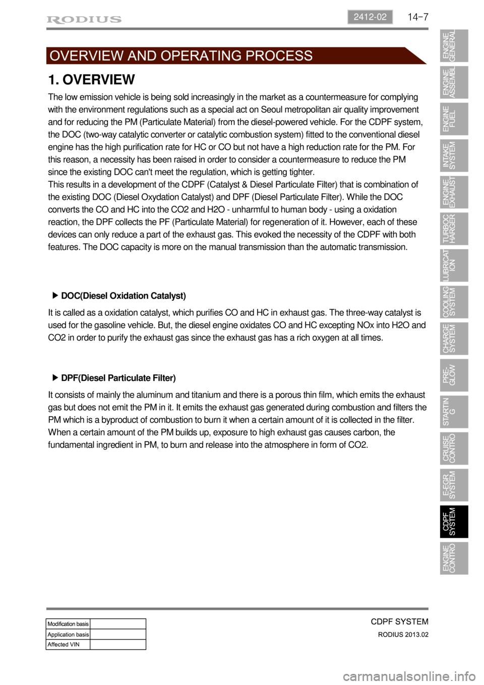
1. OVERVIEW
The low emission vehicle is being sold increasingly in the market as a countermeasure for complying
with the environment regulations such as a special act on Seoul metropolitan air quality improvement
and for reducing the PM (Particulate Material) from the diesel-powered vehicle. For the CDPF system,
the DOC (two-way catalytic converter or catalytic combustion system) fitted to the conventional diesel
engine has the high purification rate for HC or CO but not have a high reduction rate for the PM. For
this reason, a necessity has been raised in order to consider a countermeasure to reduce the PM
since the existing DOC can't meet the regulation, which is getting tighter.
This results in a development of the CDPF (Catalyst & Diesel Particulate Filter) that is combination of
the existing DOC (Diesel Oxydation Catalyst) and DPF (Diesel Particulate Filter). While the DOC
converts the CO and HC into the CO2 and H2O - unharmful to human body - using a oxidation
reaction, the DPF collects the PF (Particulate Material) for regeneration of it. However, each of these
devices can only reduce a part of the exhaust gas. This evoked the necessity of the CDPF with both
features. The DOC capacity is more on the manual transmission than the automatic transmission.
DOC(Diesel Oxidation Catalyst) ▶
It is called as a oxidation catalyst, which purifies CO and HC in exhaust gas. The three-way catalyst is
used for the gasoline vehicle. But, the diesel engine oxidates CO and HC excepting NOx into H2O and
CO2 in order to purify the exhaust gas since the exhaust gas has a rich oxygen at all times.
DPF(Diesel Particulate Filter) ▶
It consists of mainly the aluminum and titanium and there is a porous thin film, which emits the exhaust
gas but does not emit the PM in it. It emits the exhaust gas generated during combustion and filters the
PM which is a byproduct of combustion to burn it when a certain amount of it is collected in the filter.
When a certain amount of the PM builds up, exposure to high exhaust gas causes carbon, the
fundamental ingredient in PM, to burn and release into the atmosphere in form of CO2.
Page 321 of 796
14-92412-02
Differential Pressure Sensor
Calculates the amount of PM
collected by reading the pressure
difference between pre-CDPF and
post-CDPF.Engine ECU (D20DTR)
Post injection
Electric Throttle Body
Regulates the air intake
rate.CDPF
(DOC+DPF)Front EGT Sensor
Measures the combustion
temperature.
Rear EGT Sensor
Measures the CDPF
temperature.
2. COMPONENTS
For details, refer to section "Engine Control". *
Page 323 of 796

14-112412-02
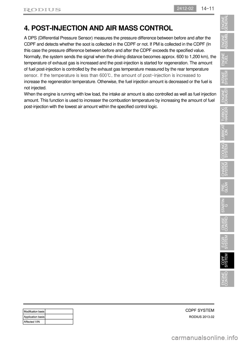
4. POST-INJECTION AND AIR MASS CONTROL
A DPS (Differential Pressure Sensor) measures the pressure difference between before and after the
CDPF and detects whether the soot is collected in the CDPF or not. If PM is collected in the CDPF (In
this case the pressure difference between before and after the CDPF exceeds the specified value.
Normally, the system sends the signal when the driving distance becomes approx. 600 to 1,200 km), the
temperature of exhaust gas is increased and the post-injection is started for regeneration. The amount
of fuel post-injection is controlled by the exhaust gas temperature measured by the rear temperature
sensor. If the temperature is less than 600℃, the amount of post-injection is increased to
increase the regeneration temperature. Otherwise, the fuel injection amount is decreased or the fuel is
not injected.
When the engine is running with low load, the intake air amount is also controlled as well as fuel injection
amount. This function is used to increaser the combustion temperature by increasing the amount of fuel
post-injection with the lowest air amount within the specified control logic.
Page 324 of 796

14-12
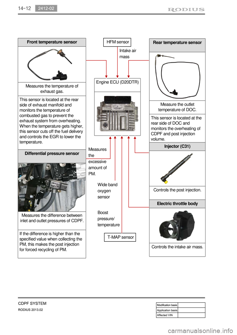
Rear temperature sensor
Measure the outlet
temperature of DOC.
This sensor is located at the
rear side of DOC and
monitors the overheating of
CDPF and post injection
volume.
Differential pressure sensor
Measures the difference between
inlet and outlet pressures of CDPF.
If the difference is higher than the
specified value when collecting the
PM, this makes the post injection
for forced recycling of PM.
Front temperature sensor
Measures the temperature of
exhaust gas.
This sensor is located at the rear
side of exhaust manifold and
monitors the temperature of
combusted gas to prevent the
exhaust system from overheating.
When the temperature gets higher,
this sensor cuts off the fuel delivery
and controls the EGR to lower the
temperature.
Engine ECU (D20DTR)
T-MAP sensorIntake air
mass
Measures
the
excessive
amount of
PM.
Injector (C31)
Controls the post injection.
Electric throttle body
Controls the intake air mass.
HFM sensor
Wide band
oxygen
sensor
Boost
pressure/
temperature
Page 325 of 796
14-132412-02
Collecting PM
→ Regeneration
The engine ECU detects the
amount of PM collected by the
information from the
temperature sensors and
differential pressure sensor.
When the soot is accumulated,
the engine ECU performs post-
injection to increase the
exhaust gas temperature and
burns the collected PM at
approx. 600°C.Oxidation (DOC)
When the exhaust gas enters
into the CDPF assembly, its
CO, HC and PM are reduced
by the redox reaction of the
DOC. The remaining PM is
filtered and collected in CDPF,
and the temperature of the
exhaust gas is increased to
between 450 and 500°C.
5. OPERATING PROCESS
[Configuration and principle of operation]
The exhaust gas
passed through the
exhaust manifold
enters into the CDPF
assembly (at approx
250℃).
Page 329 of 796
14-172412-02
4) Fuel Injection During CDPF Regeneration
The injection method in D20DTR engine has three steps;
Pilot injection, Main injection, Post injection
Post injection ▶
The post injection is the injection process after main injection and consists of ‘After injection”,
“Post 1 injection” and “Post 2 injection”. All of post injections are to reduce the PM and
harmful exhaust gas. The post injection does not make the actual output. The post injection activates
the fuel by injecting the fuel to the incompletely combusted gas after primary combustion. Through the
process, the PM and smoke in the exhaust gas could be reduced. There are totally 7 injections as
shown in the figure. However, all of 7 injections are not performed during driving because it decreases
the fuel economy. Totally 5 injections can be performed in one cycle.
Page 331 of 796
15-30000-00
1. ENGINE DATA LIST
Data Unit Value
Coolant temperature℃ 130℃~-40℃
Intake air temperature℃ -40 to 130℃ (varies by ambient air
temperature or engine mode)
Idle speed rpm 750 ± 50 (P/N)
Engine load % 18~25%
Mass air flow kg/h 16 to 25 kg/h
Throttle position angle°TA 0° (Full Open) to 78° (Close)
Engine torque Nm varies by engine conditions
Injection time ms 3 to 5ms
Battery voltage V 13.5 V to 14.1 V
Accelerator pedal position 1 V 0.4. to 4.8V
Accelerator pedal position 2 V 0.2 to 2.4 V
Throttle position 1 V 0.3 to 4.6 V
Throttle position 2 V 0.3 to 4.6 V
Oxygen sensor V 0 to 5 V
A/C compressor switch
1=ON / 0=OFF -
Full load 1=ON / 0=OFF -
Gear selection (A/T) 1=ON / 0=OFF -
Knocking control 1=ON / 0=OFF -
Brake switch 1=ON / 0=OFF -
Cruise control 1=ON / 0=OFF -
Page 339 of 796

15-110000-00
2) ECU Control
(1) Function
a. ECU Function
ECU receives and analyzes signals from various sensors and then modifies those signals into
permissible voltage levels and analyzes to control respective actuators.
ECU microprocessor calculates injection period and injection timing proper for engine piston speed
and crankshaft angle based on input data and stored specific map to control the engine power and
emission gas.
Output signal of the ECU microprocessor drives pressure control valve to control the rail pressure and
activates injector solenoid valve to control the fuel injection period and injection timing; so controls
various actuators in response to engine changes. Auxiliary function of ECU has adopted to reduce
emission gas, improve fuel economy and enhance safety, comforts and conveniences. For example,
there are EGR, booster pressure control, autocruise (export only) and immobilizer and adopted CAN
communication to exchange data among electrical systems (automatic T/M and brake system) in the
vehicle fluently. And Scanner can be used to diagnose vehicle status and defectives.
Operating temperature range of ECU is normally -40 to +85°C and protected from factors like
oil, water and electromagnetism and there should be no mechanical shocks.
To control the fuel volume precisely under repeated injections, high current should be applied instantly
so there is injector drive circuit in the ECU to generate necessary current during injector drive stages.
Current control circuit divides current applying time (injection time) into full-in-current-phase and hold-
current-phase and then the injectors should work very correctly under every working condition.
b. Control Function
Controls by operating stages
To make optimum combustion under every operating stage, ECU should calculate proper injection
volume in each stage by considering various factors.
Starting injection volume control
During initial starting, injecting fuel volume will be calculated by function of temperature and engine
cranking speed. Starting injection continues from when the ignition switch is turned to ignition
position to till the engine reaches to allowable minimum speed.
Driving mode control
If the vehicle runs normally, fuel injection volume will be calculated by accelerator pedal travel and
engine rpm and the drive map will be used to match the drivers inputs with optimum engine power. -
-
-