Page 628 of 751
11-26
4) RISE (ESP is working) Mode
The shuttle valve and inlet valve will be open and the separation valve and outlet valve will be closed.
Then, the pump is operated. When ESP operates while the ABS is operating, the pressure will be
increased continuously until just before the corresponding wheel gets locked.
Page 629 of 751
11-274890-10
5) Hydraulic Circuit of HBA
The above figure shows one front and one rear wheel and the same hydraulic circuit forms as in the
ESP operation. When HECU recognizes that it is an emergency and it is required for hard braking,
depending on the pressure value of the brake pressure sensor and pressure changes caused by the
pressure sensor timing, it operates the pump immediately to apply the brake pressure at the wheels.
Then, the pressure in the pump increases until just before the corresponding wheel gets locked. The
motor still keeps rotating and the outlet valve and the separation valve will stay closed. When the wheel
starts to lock, the HBA function cancels and switches to ABS operation.
Page 674 of 751

14-134170-09
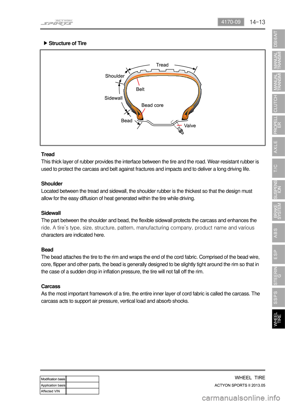
Structure of Tire ▶
Tread
This thick layer of rubber provides the interface between the tire and the road. Wear-resistant rubber is
used to protect the carcass and belt against fractures and impacts and to deliver a long driving life.
Shoulder
Located between the tread and sidewall, the shoulder rubber is the thickest so that the design must
allow for the easy diffusion of heat generated within the tire while driving.
Sidewall
The part between the shoulder and bead, the flexible sidewall protects the carcass and enhances the
<00990090008b008c0055004700680047009b00900099008c02c5009a0047009b00a00097008c00530047009a009000a1008c00530047009a009b0099009c008a009b009c0099008c0053004700970088009b009b008c009900950053004700940088009500
9c008d0088008a009b009c009900900095008e0047008a0096>mpany, product name and various
characters are indicated here.
Bead
The bead attaches the tire to the rim and wraps the end of the cord fabric. Comprised of the bead wire,
core, flipper and other parts, the bead is generally designed to be slightly tight around the rim so that in
the case of a sudden drop in inflation pressure, the tire will not fall off the rim.
Carcass
As the most important framework of a tire, the entire inner layer of cord fabric is called the carcass. The
carcass acts to support air pressure, vertical load and absorb shocks.
Page 704 of 751
01-256810-01
6. A/C COOLING CYCLE
1) System Flow
"Compression -> Condensation -> Expansion -> Evaporation" -
2) Functions
(1) Compressor
Condition: Gas
Function: Circulates the refrigerant and increases the pressure and temperature for easier
evaporation. -
-
(2) Condenser
Condition: Gas/Liquid
Function: Cools and condenses the refrigerant by using ambient air to liquefy it under high pressure. -
-
(3) Receiver drier
Condition: Gas/Liquid
Function: Keeps the refrigerant free from moisture by separating/collecting the moisture from it. -
-
(4) Expansion valve
Condition: Liquid/Liquefied gas
Function: Performs adiabatic expansion and flow control for easier evaporation. -
-
(5) Evaporator
Condition: Liquefied gas/Gas
Function: Cools the air by absorbing the heat from the air around the evaporator. -
-
Page 705 of 751

01-26
3) Description for Each Cycle
(1) Compression
The evaporated refrigerant in the evaporator enters to the compressor. And the refrigerant gas is
compressed until it can be liquefied at ambient temperature.
Thus, the low refrigerant pressure is maintained so that the liquid refrigerant can be evaporated
actively at low temperature (around 0 ℃). -
-
(2) Condensation
The high pressure and high temperature gas (refrigerant) from the compressor is cooled down by the
fresh air entered into the condenser. Then, this gas is converted to liquid and collected in the receiver
drier.
The heat generated from the high pressure refrigerant is dissipated to the ambient air, and it is called
"heat of condensation".
The heat of condensation is the summation of the heat of vaporization (heat that the refrigerant
absorbs from the inside of the vehicle) and the calorific value converted from the amount of work
which is needed to compress. -
-
(3) Expansion
The liquid refrigerant lowers the pressure making its evaporation easily accomplished.
This process (lowering the pressure to the level at which evaporation easily takes place before the
liquid refrigerant is sent to the evaporator) is called
"Adiabatic Expansion".
During adiabatic expansion, the expansion valve lowers the pressure of the refrigerant and
determines the correct amount of refrigerant going into the air conditioning evaporator.
That is, the amount of heat, which is needed to stop the evaporation, is determined according to the
cooling load.
The expansion valve detects this and regulates the amount of the refrigerant exactly. -
-
(4) Evaporator
The refrigerant is converted from liquid to gas in the evaporator.
(The refrigerant in the form of fog in the evaporator is vaporized actively)
At this time the refrigerant, in the form of liquid, absorbs the heat in the air which is need for
evaporation (latent heat) and is cooled down. Then the blower blows the cooled air inside the vehicle
to lower the temperature.
There are liquid refrigerant from the expansion valve and evaporated refrigerant in the evaporator.
The evaporation temperature can be predicted from the evaporation pressure (i.e. relationship
between saturation pressure and saturation temperature).
It is important to keep the pressure inside the evaporator low, so that the refrigerant is evaporated at
low temperature to make sure the completely evaporated refrigerant is entered into the compressor. -
-
-
-
-
Page 723 of 751

02-14
4. DEPLOYMENT
According to the collision deceleration rate that each collision G sensor reads, the air bag unit sends out
about 2~4 or higher Amp current. This current generates some heat, which fires the detonator in the
inflator.
The table shows the basic inner resistance of the air bag related module and the basic instant current
necessary for firing.
1) Air Bag System Deployment (Firing Loop)
2) Air Bag Deployment Signal Output (Crash Out)
When the air bag deploys, the signal is sent to STICS to perform the basic security operation which is
the automatic door unlock function that release the automatic door lock mode.
Deployment signal
output (crash out)200ms
Automatic Door Unlock (Crash unlock: unlock when colliding) ▶
The air bag collision signal input cannot be accepted within 7 seconds after turning the ignition key to
"ON" position.
After this period, the door lock system outputs "UNLOCK" for all doors for 5 seconds from 40 ms after
receiving the air bag collision signal.
Even though the key is turned to "OFF" position during the output of "UNLOCK", the output continues
on for remaining period.
The function is erased when turning "OFF" the ignition switch. 1.
2.
3.
4.
Air bag module
DAB /PABSeat belt pretensioner(BPA)
Resistance (at -30 ~ 85˚C) 2 ±0.3 Ω 2.15 ±0.35 Ω
Firing current 1.2 Amps 0.8 Amps
Please do not connect a tester to any air bag connector or single item to measure the supplied
power or resistance. The detonator may explode due to a sudden extra power supplied by the
tester.
Before removing or installing any air bag related components, disconnect the negative battery
cable. -
-