Page 501 of 751

02-33170-01
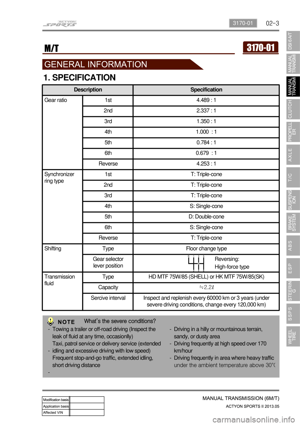
Description Specification
Gear ratio 1st 4.489 : 1
2nd 2.337 : 1
3rd 1.350 : 1
4th 1.000 : 1
5th 0.784 : 1
6th 0.679 : 1
Reverse 4.253 : 1
Synchronizer
ring type1st T: Triple-cone
2nd T: Triple-cone
3rd T: Triple-cone
4th S: Single-cone
5th D: Double-cone
6th S: Single-cone
Reverse T: Triple-cone
Shifting Type Floor change type
Gear selector
lever position
Transmission
fluidType HD MTF 75W/85 (SHELL) or HK MTF 75W/85(SK)
Capacity≒2.2ℓ
Sercive interval Inspect and replenish every 60000 km or 3 years (under
severe driving conditions, change every 120,000 km)
1. SPECIFICATION
Reversing:
High-force type
What’s the severe conditions?
Towing a trailer or off-road driving (Inspect the
leak of fluid at any time, occasionlly)
Taxi, patrol service or delivery service (extended
idling and excessive driving with low speed)
Frequent stop-and-go traffic, extended idling,
short driving distance -
-
-Driving in a hilly or mountainous terrain,
sandy, or dusty area
Driving frequently at high speed over 170
km/hour
Driving frequently in area where heavy traffic
under the ambient tem
perature above 30°C
-
-
-
Page 502 of 751

02-4
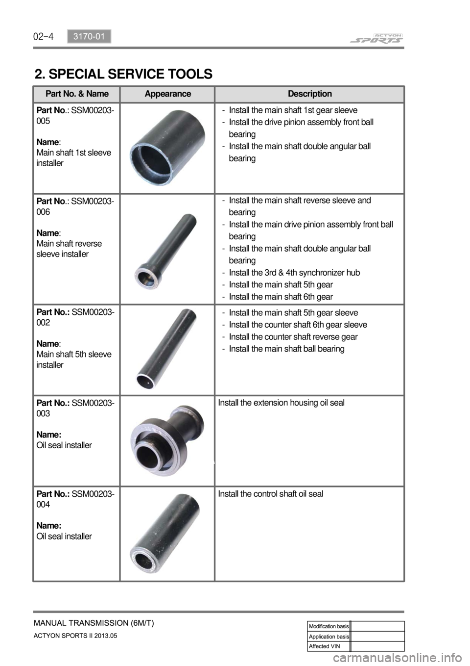
Part No. & Name Appearance Description
Part No.: SSM00203-
005
Name:
Main shaft 1st sleeve
installer
Part No.: SSM00203-
006
Name:
Main shaft reverse
sleeve installer
Part No.: SSM00203-
002
Name:
Main shaft 5th sleeve
installer
Part No.: SSM00203-
003
Name:
Oil seal installerInstall the extension housing oil seal
Part No.: SSM00203-
004
Name:
Oil seal installerInstall the control shaft oil seal
2. SPECIAL SERVICE TOOLS
Install the main shaft reverse sleeve and
bearing
Install the main drive pinion assembly front ball
bearing
Install the main shaft double angular ball
bearing
Install the 3rd & 4th synchronizer hub
Install the main shaft 5th gear
Install the main shaft 6th gear -
-
-
-
-
-Install the main shaft 1st gear sleeve
Install the drive pinion assembly front ball
bearing
Install the main shaft double angular ball
bearing -
-
-
Install the main shaft 5th gear sleeve
Install the counter shaft 6th gear sleeve
Install the counter shaft reverse gear
Install the main shaft ball bearing -
-
-
-
Page 503 of 751
02-53170-01
Part No. & Name Appearance Description
Part No.: SSM00203-
001
Name:
Counter shaft
bearing installerInstall the counter shaft front roller bearing
Part No.:
T88310011A-9
Name:
Bearing supportSupport the counter shaft when removing the roller
bearing with a puller
Special service tool Supplier: Tool & Tech *
Page 547 of 751

08-10
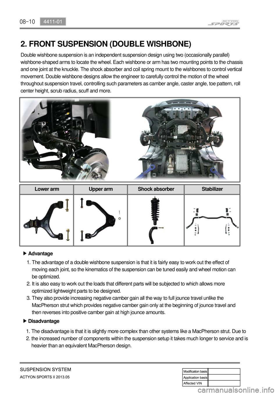
2. FRONT SUSPENSION (DOUBLE WISHBONE)
Advantage ▶
The advantage of a double wishbone suspension is that it is fairly easy to work out the effect of
moving each joint, so the kinematics of the suspension can be tuned easily and wheel motion can
be optimized.
It is also easy to work out the loads that different parts will be subjected to which allows more
optimized lightweight parts to be designed.
They also provide increasing negative camber gain all the way to full jounce travel unlike the
MacPherson strut which provides negative camber gain only at the beginning of jounce travel and
then reverses into positive camber gain at high jounce amounts. 1.
2.
3.
Disadvantage ▶
The disadvantage is that it is slightly more complex than other systems like a MacPherson strut. Due to
the increased number of components within the suspension setup it takes much longer to service and is
heavier than an equivalent MacPherson design. 1.
2. Double wishbone suspension is an independent suspension design using two (occasionally parallel)
wishbone-shaped arms to locate the wheel. Each wishbone or arm has two mounting points to the chassis
and one joint at the knuckle. The shock absorber and coil spring mount to the wishbones to control vertical
movement. Double wishbone designs allow the engineer to carefully control the motion of the wheel
throughout suspension travel, controlling such parameters as camber angle, caster angle, toe pattern, roll
center height, scrub radius, scuff and more.
Lower arm Upper arm Shock absorber Stabilizer
Page 552 of 751

09-34850-01
1. SPECIFICATION
Unit Description Specification
Front brake Type Ventilated disc
Outer diameter of discØ294 mm
Inner diameter of caliper cylinderØ43.0 x 2 mm
Thickness of disc 28 mm (wear limit: 25.4 mm)
Area of brake pad Above 60 cm2
Pad wear indicator Mechanical type
Rear brake Type Solid disc
Outer diameter of discØ299 m
Thickness of disc 10.4 mm (wear limit: 8.5 mm)
Area of brake pad Above 28.8 cm2
Pad wear indicator Mechanical type
Brake booster Type Vacuum assist type
Size8” + 9” (Tandem)
Master cylinder Type Tandem type(integrated level sensor)
Inner diameter of cylinderØ26.99 mm
Brake pedal Maximum operating stroke 150 mm
Pedal ratio 4 : 1
Free play 3 to 10 mm
Parking brake Type Mechanically expanded rear lining
Operating type Hand operated type
Inner diameter of drumØ190 mm
Brake oil Specification DOT 4
Capacity As required
Service Interval: Change the brake oil at every 2 years
DOT?
It is the quality grade of brake fluid established by US Department of Transportation.
Page 566 of 751
09-174850-01
Brake Fluid ▶
Brake Fluid Type ▶ 1. Color
Ligh gold (New oil) → Brown → Black -
2. Service Interval/Type
Change: every 2 years, Type: DOT4
The water in the brake fluid has an adverse effect to the brake system. If the fluid contains
around 3% of water, the boiling point of the brake fluid goes down by 25%. It will cause the vapor
lock frequently.
Water content in fluid: around 3% after 18 months, around 7~10% after few years
The water ib fluid makes the corrosion in the brake lines, deforms and deteriorates the rubber
components, brake calipers and pistons. -
DOT4: Brake fluid for premium vehicle. Lower water absorbing rate AND higher boiling point than
DOT3
Brake Fluid Level Check ▶
The brake fluid level should be between "MAX"
and "MIN" on the reservoir. If it is below "MIN"
mark, check for oil leaks and refill the reservoir
with the specified fluid.
Page 632 of 751
12-34610-01
1. SPECIFICATIONS
Description Specification
Steering wheel Type 4-spoke type
Gear box
(HPS)Type Rack and pinion type
Gear ratio 40.245
Steering angle Inner36.2˚
Outer32.4˚
Oil pump
(HPS)Type Vane type
Maximum pressure (kgf/cm2)90 ± 3
Pulley size (mm)Ø115
Operating temperature-40℃~150℃
Minimum turning radius (m) 5.8
Steering oil Type S-PSF-3
Capacity (L) Approx. 1.0
Service interval Daily check and add if necessary.
Steering column shaft Tilting angle-4.0/ 0° /+4.0° / +8.0°
This section describes the power steering pump and gear box based on the HPS (Hydraulic Power
Steering) system. For the information of the SSPS (Speed Sensing Power Steering) system, refer to
SSPS section under CHASSIS.
Page 648 of 751
12-194610-01
Oil Pump Pressure Check ▶
Unscrew the pressure line fitting in power
steering pump.
Install the pressure gauge between the
power steering pump and the power steering
oil pressure line.
Place the shift lever to neutral position. Apply
the parking brake.
Open the valve in pressure gauge. Start the
engine and let it run at idle speed.
Turn the steering wheel several times so that
the oil temperature reaches to normal
operating level. 1.
2.
3.
4.
5.
Before checking the pressure, check the oil
level and belt tension. Prepare the empty
container to collect the spilled oil during the
service. Check the oil pump pressure to locate any
defect in oil pump.
Fully close the valve in pressure gauge and
measure the oil pressure. 6.
Relief pressure
90 ± 3 bar
Oil pump
Steering gear box
To prevent internal damage, do not close
the gauge valve over 10 seconds.
Keep the oil temperature at proper range. -
-