Page 520 of 751
04-4
1. OVERVIEW
The hydraulic clutch transmits the force required to operate the clutch pedal to the concentric slave
cylinder fitted to the clutch housing as a hydraulic pressure.
(The hydraulic pressure is transmitted in the following order: Clutch pedal - Clutch master cylinder -
Clutch pipe - Clutch damper - Clutch pipe and hose - Concentric slave cylinder - Pressure plate -
Flywheel.)
If a driver depress the clutch pedal, the hydraulic pressure is generated in the master cylinder. It is
transmitted to the concentric slave cylinder through the pipe, resulting in the cylinder being forced out. At
this time, the clutch disc is forced against the cylinder by pushing the cover. This, in turn, remove the
flywheel from the pressure plate. As a consequence, the power from the engine will be cut off and the
gear change can be carried out.
Page 522 of 751

04-6
2) Overview
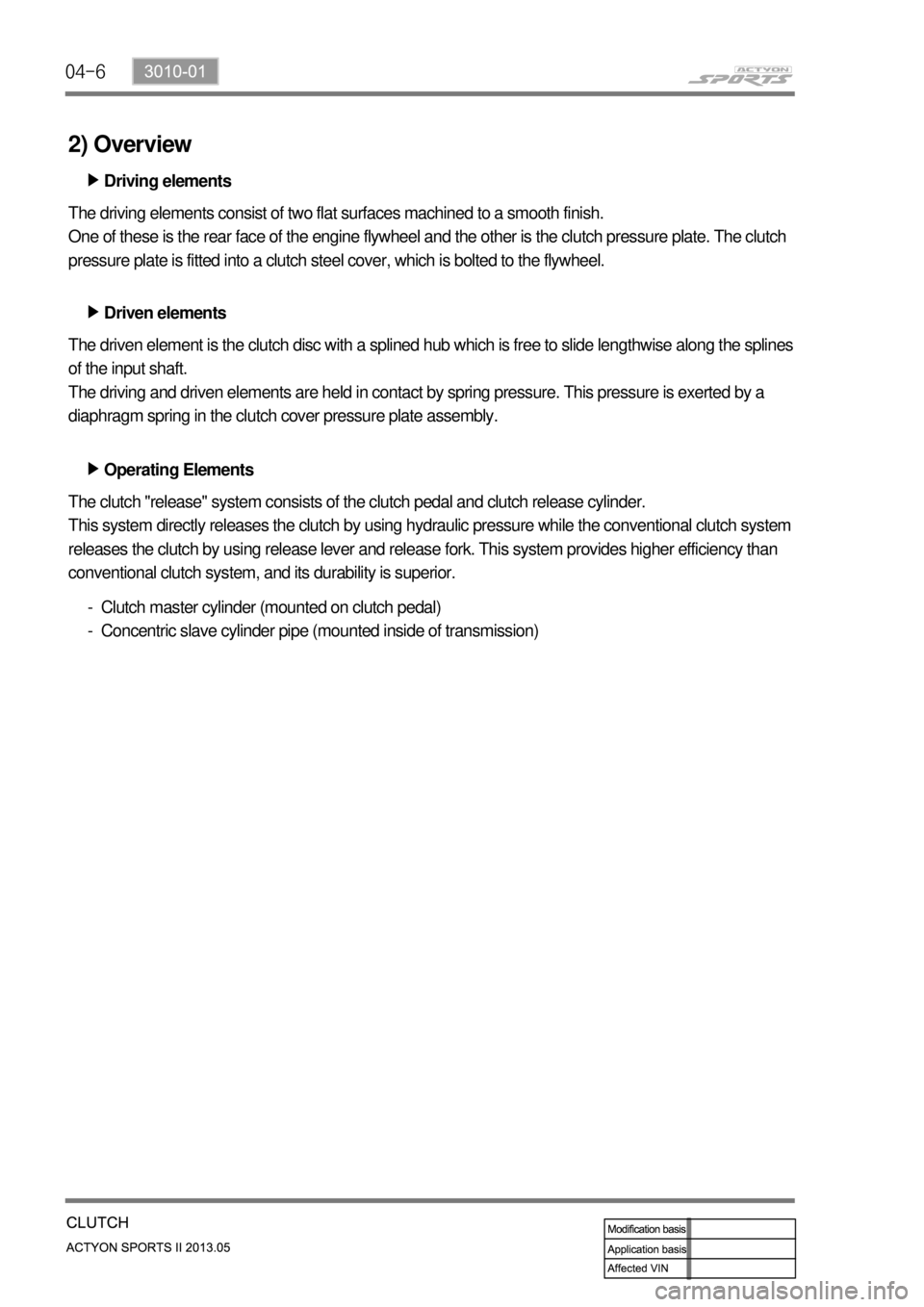
Driving elements ▶
The driving elements consist of two flat surfaces machined to a smooth finish.
One of these is the rear face of the engine flywheel and the other is the clutch pressure plate. The clutch
pressure plate is fitted into a clutch steel cover, which is bolted to the flywheel.
Driven elements ▶
The driven element is the clutch disc with a splined hub which is free to slide lengthwise along the splines
of the input shaft.
The driving and driven elements are held in contact by spring pressure. This pressure is exerted by a
diaphragm spring in the clutch cover pressure plate assembly.
Operating Elements ▶
The clutch "release" system consists of the clutch pedal and clutch release cylinder.
This system directly releases the clutch by using hydraulic pressure while the conventional clutch system
releases the clutch by using release lever and release fork. This system provides higher efficiency than
conventional clutch system, and its durability is superior.
Clutch master cylinder (mounted on clutch pedal)
Concentric slave cylinder pipe (mounted inside of transmission) -
-
Page 524 of 751
04-8
3. DUAL MASS FLYWHEEL (DMF)
The dual mass flywheel (DMF) is of having a mass divided into two halves.
While one mass is connected to the engine crankshaft, which is affected by the mass moment of inertia
of the engine, the other mass is affected by one of the transmission.
The divided dual masses are connected to the coil spring and damping system internally.
The DMF has the following benefits: ▶
Reducing fuel consumption by lowering engine speed
Reducing rattling noise and vehicle vibration in all driving ranges
Reducing synchronization wear
Facilitating gear change
Protecting power train parts by preventing excessive load from being delivered -
-
-
-
-
Primary flywheel
Secondary flywheel
Arc damper spring
Torque limiter
Ring gear 1.
2.
3.
4.
5.
Page 547 of 751

08-10
2. FRONT SUSPENSION (DOUBLE WISHBONE)
Advantage ▶
The advantage of a double wishbone suspension is that it is fairly easy to work out the effect of
moving each joint, so the kinematics of the suspension can be tuned easily and wheel motion can
be optimized.
It is also easy to work out the loads that different parts will be subjected to which allows more
optimized lightweight parts to be designed.
They also provide increasing negative camber gain all the way to full jounce travel unlike the
MacPherson strut which provides negative camber gain only at the beginning of jounce travel and
then reverses into positive camber gain at high jounce amounts. 1.
2.
3.
Disadvantage ▶
The disadvantage is that it is slightly more complex than other systems like a MacPherson strut. Due to
the increased number of components within the suspension setup it takes much longer to service and is
heavier than an equivalent MacPherson design. 1.
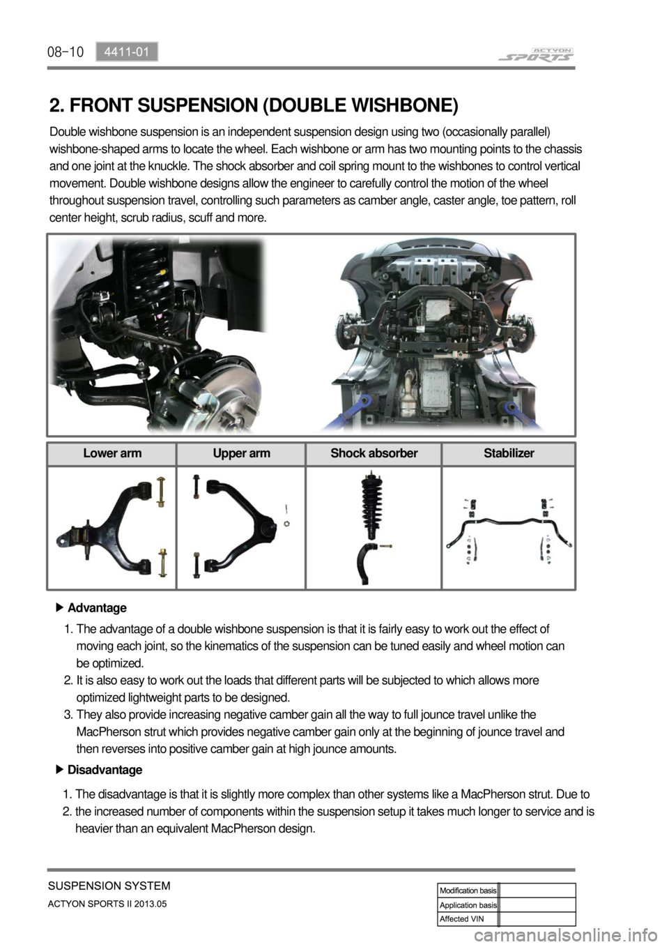
2. Double wishbone suspension is an independent suspension design using two (occasionally parallel)
wishbone-shaped arms to locate the wheel. Each wishbone or arm has two mounting points to the chassis
and one joint at the knuckle. The shock absorber and coil spring mount to the wishbones to control vertical
movement. Double wishbone designs allow the engineer to carefully control the motion of the wheel
throughout suspension travel, controlling such parameters as camber angle, caster angle, toe pattern, roll
center height, scrub radius, scuff and more.
Lower arm Upper arm Shock absorber Stabilizer
Page 558 of 751
09-94850-01
Problem Cause Action
Burning smell around
tireToo frequent braking in high driving speed Reduce the use of
foot brake/use
engine brake
properly Used only foot brake during downhill driving
Driving with foot on brake pedal Get off the foot from
pedal
Foreign materials such as dirt or sand in brake system Replace: caliper,
wheel cylinder,
master cylinder,
return spring
Broken return spring in shoe assembly Replace
Incorrectly adjusted parking brake cable Adjust
Incorrect wheel or wheel cover
(generating the heat)Replace
Page 559 of 751

09-10
This section describes the noise phenomena occurred possibly in the brake system operation.
Distinguish between the information given below and the actual problems and then, inspect the vehicle
and take appropriate measures.
Noise symptoms and Causes -
Symptom 1. If depressing the brake pedal when the engine is cold, "screeching" sound always
occurs and, after driving for a while, the sound disappears..
This usually occurs in the morning. When the temperature goes down, the dew condensation
phenomenon sets moisture on the brake disc as the window frost forms. Due to this moisture, the iron
within the brake disc and pad oxidizes, forming undetectable micro-rusts on the disc surface. When
starting the engine under this condition, noise may sound due to the friction of micro-rusts. When
operating the brake several times, the disc temperature goes up and the micro-rusts come off and the
noise goes away. Depending on the driving conditions, noise gets louder when slightly depressing the
brake pedal and oppositely, noise is smaller when deeply depressing the brake pedal. This is simply a
physical phenomenon, called "morning effect" in professional terms, and does not imply any problems
with the brake system.
Symptom 2. Slip or screech after the brake pad replacement.
This usually occurs when the bed-in is not made between the disc and the pad's friction material. The
bed-in is a state that the brake system normally works and gives no noise out, when, after about 300 km
city driving, the contact area of the pad friction material is enlarged and the disk is in complete contact
with the pad's friction material. Therefore, for some time after the brake disk/pad replacement, the brake
system poorly operates or noise (abnormal sound) occurs due to the partial contact.
Symptom 3. "Groaning" sound occurs in the automatic transmission vehicle when slightly taking the foot
off the brake pedal to slowly start after waiting for the signal, or slightly depressing the brake pedal.
This is the noise "Creep groan" that occurs when, in both the automatic and manual transmission,
slightly releasing the brake pedal in the neutral gear at downhill roads.
It frequently occurs at the low braking power and low speed, through the following process. When
operating the brake system at low speed and low pressure, adhesion and slip repeatedly take place
between the brake disk and the friction material, and this makes the braking power inconstant, instantly
increasing or decreasing, and gives out the brake noise.
It is also a physical phenomenon and has no relation with the brake performance.BRAKE OPERATION AND NOISE ▶
Page 562 of 751
09-134850-01
Maximum Stroke of Brake Pedal ▶
Check the brake pedal with below procedures: -
Start the engine.
Pump the brake pedal around 3 times.
Depress the brake pedal with approx. 30 kg
and measure the distance (A) between the
upper surface of pedal pad and the lower
dash panel.
If the measured value is out of the specified
value, adjust the length. 1.
2.
3.
4.
Specified value (A)150mm
5. BRAKE SYSTEM CHECK
Over the specified value
Cause Action
Worn brake pad Replace
Worn brake shoe Replace
Improper stroke of hand
brakeAdjust
Air in brake line Air bleeding
Oil leak Repair or replace
Brake booster push rod Replace or adjust
Improperly adjusted
stopper boltAdjust
Below the specified value
Cause Action
Brake booster push rod
Replace or adjust
Air in brake fluid Replace
Improperly adjusted
stopper boltAdjust
Page 563 of 751
09-14
Specified value (B)155mm
Push rod
Stop lamp
switch Pedal Height ▶
Check the pedal height with below procedures: -
Start the engine and measure the length (A)
between floor mat and pedal.
If the measured value is out of the specified
value, adjust the length. 1.
2.
Adjust the pedal height with below procedures: -
Disconnect the stop lamp switch connector.
Unscrew the lock nut and remove the stop
lamp switch assembly.
Loosen the lock nut on the pedal push rod.
Turn the pedal push rod to adjust the pedal
height.
Tighten the lock nut.
Install the stop lamp switch assembly.
Connect the stop lamp switch connector.
Check if the stop lamps come on when
pressing the brake pedal around 5 mm.
If the stop lamp dpes not come on, adjust the
stop lamp switch assembly again.
If the stop lamps come on, tighten the lock nut
and measure the pedal height again. 1.
2.
3.
4.
5.
6.
7.
8.
9.
10.