Page 119 of 751

06-50000-00
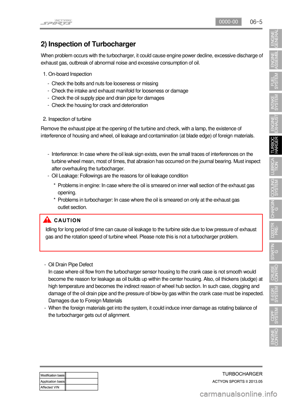
2) Inspection of Turbocharger
When problem occurs with the turbocharger, it could cause engine power decline, excessive discharge of
exhaust gas, outbreak of abnormal noise and excessive consumption of oil.
On-board Inspection 1.
Check the bolts and nuts foe looseness or missing
Check the intake and exhaust manifold for looseness or damage
Check the oil supply pipe and drain pipe for damages
Check the housing for crack and deterioration -
-
-
-
Inspection of turbine 2.
Remove the exhaust pipe at the opening of the turbine and check, with a lamp, the existence of
interference of housing and wheel, oil leakage and contamination (at blade edge) of foreign materials.
Interference: In case where the oil leak sign exists, even the small traces of interferences on the
turbine wheel mean, most of times, that abrasion has occurred on the journal bearing. Must inspect
after overhauling the turbocharger.
Oil Leakage: Followings are the reasons for oil leakage condition -
-
Idling for long period of time can cause oil leakage to the turbine side due to low pressure of exhaust
gas and the rotation speed of turbine wheel. Please note this is not a turbocharger problem.
Oil Drain Pipe Defect
In case where oil flow from the turbocharger sensor housing to the crank case is not smooth would
become the reason for leakage as oil builds up within the center housing. Also, oil thickens (sludge) at
high temperature and becomes the indirect reason of wheel hub section. In such case, clogging and
damage of the oil drain pipe and the pressure of blow-by gas within the crank case must be inspected.
Damages due to Foreign Materials
When the foreign materials get into the system, it could induce inner damage as rotating balance of
the turbocharger gets out of alignment. -
-Problems in engine: In case where the oil is smeared on inner wall section of the exhaust gas
opening.
Problems in turbocharger: In case where the oil is smeared on only at the exhaust gas
outlet section. *
*
Page 139 of 751
07-51543-00
1. SYSTEM DESCRIPTION
1) Overview
The lubrication system supplies oil to each lubrication section to prevent friction and wear and to remove
heat from the friction part. As the engine runs, frictional heat is generated on each lubrication section. If
this condition persists, the bearing can be burned and stuck.
In other words, it creates an oil film on each sliding surface to convert solid friction to liquid friction in order
to minimize wear and prevent temperature increasing on the friction part.
For the D20DTF engine with no oil pressure switch, the engine ECU receives the low engine oil level
signal from the oil level sensor and communicates with the instrument cluster through the CAN
communication to turn on the warning lamp.
2) Components
Oil coolerOil dipstick gaugeOil pump
Oil filter moduleOil pressure switchOil pan
Page 142 of 751

08-4
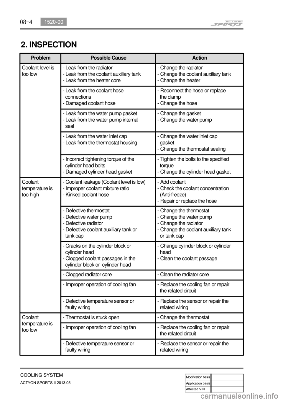
2. INSPECTION
Problem Possible Cause Action
Coolant level is
too low- Leak from the radiator
- Leak from the coolant auxiliary tank
- Leak from the heater core- Change the radiator
- Change the coolant auxiliary tank
- Change the heater
- Leak from the coolant hose
connections
- Damaged coolant hose- Reconnect the hose or replace
the clamp
- Change the hose
- Leak from the water pump gasket
- Leak from the water pump internal
seal- Change the gasket
- Change the water pump
- Leak from the water inlet cap
- Leak from the thermostat housing- Change the water inlet cap
gasket
- Change the thermostat sealing
- Incorrect tightening torque of the
cylinder head bolts
- Damaged cylinder head gasket- Tighten the bolts to the specified
torque
- Change the cylinder head gasket
Coolant
temperature is
too high- Coolant leakage (Coolant level is low)
- Improper coolant mixture ratio
- Kinked coolant hose- Add coolant
- Check the coolant concentration
(Anti-freeze)
- Repair or replace the hose
- Defective thermostat
- Defective water pump
- Defective radiator
- Defective coolant auxiliary tank or
tank cap- Change the thermostat
- Change the water pump
- Change the radiator
- Change the coolant auxiliary tank
or tank cap
- Cracks on the cylinder block or
cylinder head
- Clogged coolant passages in the
cylinder block or cylinder head- Change cylinder block or cylinder
head
- Clean the coolant passage
- Clogged radiator core - Clean the radiator core
- Improper operation of cooling fan - Replace the cooling fan or repair
the related circuit
- Defective temperature sensor or
faulty wiring- Replace the sensor or repair the
related wiring
Coolant
temperature is
too low- Thermostat is stuck open - Change the thermostat
- Improper operation of cooling fan - Replace the cooling fan or repair
the related circuit
- Defective temperature sensor or
faulty wiring- Replace the sensor or repair the
related wiring
Page 149 of 751

09-4
2. INSPECTION
1) Alternator Output Test
Item How to check DTC set value / Action
Output
current
B terminal
current
Rotor
coil
resistance
L terminal
voltage
Disconnect the cable connected to the B
terminal on the alternator. Connect one end
of the ammeter to the B terminal and the
other end to the cable connected to the B
terminal.
Measure the maximum output value.
(Maintain the engine speed between 2,500
and 3,000 rpm.)
(Turn the headlamp and all the electrical
switches on.) 1.
2.Pass: If the measured current is 45
A or higher.
Fail: If the measured current is less
than 45 A.
Check the current of the B terminal. -
-
-
Move the gear selector lever to the neutral
position.
Maintain the engine speed at 2,500 rpm
with the vehicle unloaded.
(Turn all the electrical switches off.) 1.
2.Open circuit: If the measured
current is 5 A or higher. -
Disconnect the negative cable from the
battery.
Remove the B terminal and turn off the
ignition switch.
Measure the resistance between the L and
F terminals with an ohmmeter. 1.
2.
3.Pass: If the measured resistance is
between 3 and 6 Ω.
Faulty rotor coil or slip ring: If the
measured resistance is less than
3 Ω or greater than 6 Ω. -
-
Connect the B terminal wiring.
Measure the voltage with the engine running. 1.
2.Specification: 12.5 V to 14.5 V
Faulty IC regulator or field coil: If
the measured voltage is 14.5 V or
higher. -
-
Disconnect the negative battery cable.
Connect the negative cable again after connecting the ammeter. -
-
Page 150 of 751

09-51451-01
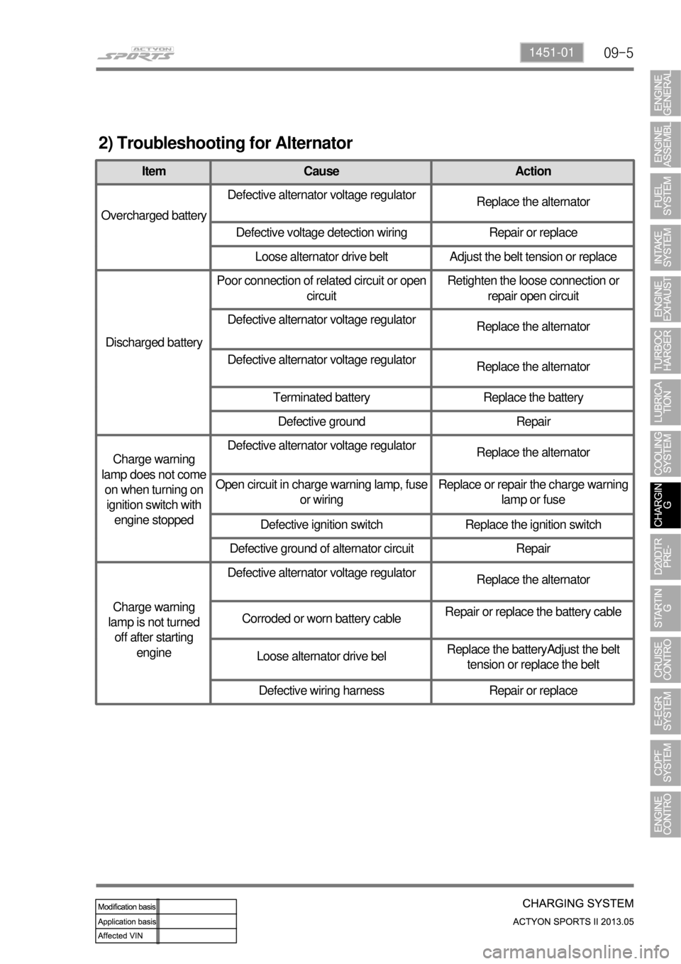
2) Troubleshooting for Alternator
Item Cause Action
Overcharged batteryDefective alternator voltage regulator
Replace the alternator
Defective voltage detection wiring Repair or replace
Loose alternator drive belt Adjust the belt tension or replace
Discharged batteryPoor connection of related circuit or open
circuitRetighten the loose connection or
repair open circuit
Defective alternator voltage regulator
Replace the alternator
Defective alternator voltage regulator
Replace the alternator
Terminated battery Replace the battery
Defective ground Repair
Charge warning
lamp does not come
on when turning on
ignition switch with
engine stoppedDefective alternator voltage regulator
Replace the alternator
Open circuit in charge warning lamp, fuse
or wiringReplace or repair the charge warning
lamp or fuse
Defective ignition switch Replace the ignition switch
Defective ground of alternator circuit Repair
Charge warning
lamp is not turned
off after starting
engineDefective alternator voltage regulator
Replace the alternator
Corroded or worn battery cableRepair or replace the battery cable
Loose alternator drive belReplace the batteryAdjust the belt
tension or replace the belt
Defective wiring harness Repair or replace
Page 154 of 751
09-91451-01
If the charge warning lamp ( ) on the instrument cluster comes on while driving, there is a
malfunction in the charge system including the battery. Therefore, carrying out the system check is
needed.
(4) Maintenance
Make sure that the battery cables are firmly connected.
If the terminals are corroded, clean them with a wire brush or sandpapers.
Always disconnect the battery cables with the ignition key removed. When disconnecting the battery
cables with the ignition key turned to ON or ACC position, several electric units can be damaged
due to sudden voltage change.
Check the battery for crack, damage or fluid leaks. Replace it if necessary.
Wipe out the battery fluid on the battery surface using a rubber glove and a clean cloth wetted with
soapy water. -
-
-
-
Page 188 of 751
14-4
2. CAUTIONS
1) Standard pattern of soot accumulation
Abnormal Soot Accumulation ▶
Normal Soot Combustion ▶
Cautions to protect the catalyst filter ▶
Use the designated fuel only.
Observe the recommended service intervals of engine oil.
Check the engine oil level frequently and add if necessary.
Do not idle the vehicle unnecessarily.
Do not turn off the engine while the vehicle is running.
Do not shift the gear selector lever to neutral when going downhill.
Do not use improper engine oil or fuel additives.
Do not drive for a long time when the warning lamp is illuminated.
Make sure no flammable material, such as dry grass or tissue paper, contacts with the catalyst filter
while the vehicle is parked.
For the vehicles used in urban traffic, driving on the expressways for more than 1 hour at least once
per week is needed so that the PM inside CDPF isn't collected to one side only. -
-
-
-
-
-
-
-
-
-
Page 189 of 751

14-52412-02
The CDPF system enters the regeneration mode
when the driving distance becomes approx. 600
to 1,200 km (may differ by the driving condition
and driving style). Then, the engine ECU
performs the CDPF regeneration operation.
However, the driver is not informed with this
operation by any engine warning lamp or vehicle
signal, so he/she may not detect this operation.
The control logic at the post-injection dur-ing the
regeneration process is to increase the fuel
injection volume and control the intake air volume
(by the throttle body) in order to increase the
temperature of the exhaust gas. The driver may
not feel any particular difference from the vehicle.
Overload of CDPF (warning lamp blinking)
2) Warning Lamp Related to CDPF
CDPF regeneration process (warning lamp NOT illuminated) ▶
If the CDPF cannot reach the regeneration temperature due to low speed driving or other reason
during the regeneration process, the soot is continuously accumulated in the CDPF. When this
condition continues and the CDPF is overloaded with soot, the engine warning lamp blinks to inform
this situation to the driver.
In order to solve this problem, drive the vehicle at a speed of approx. 80 km/h for 15 to 20 minutes to
perform the CDPF regeneration process.
If the engine warning lamp on the instrument cluster blinks, the CDPF is overloaded. In this case,
perform the step 2. 1.
2.
3.