Page 142 of 751

08-4
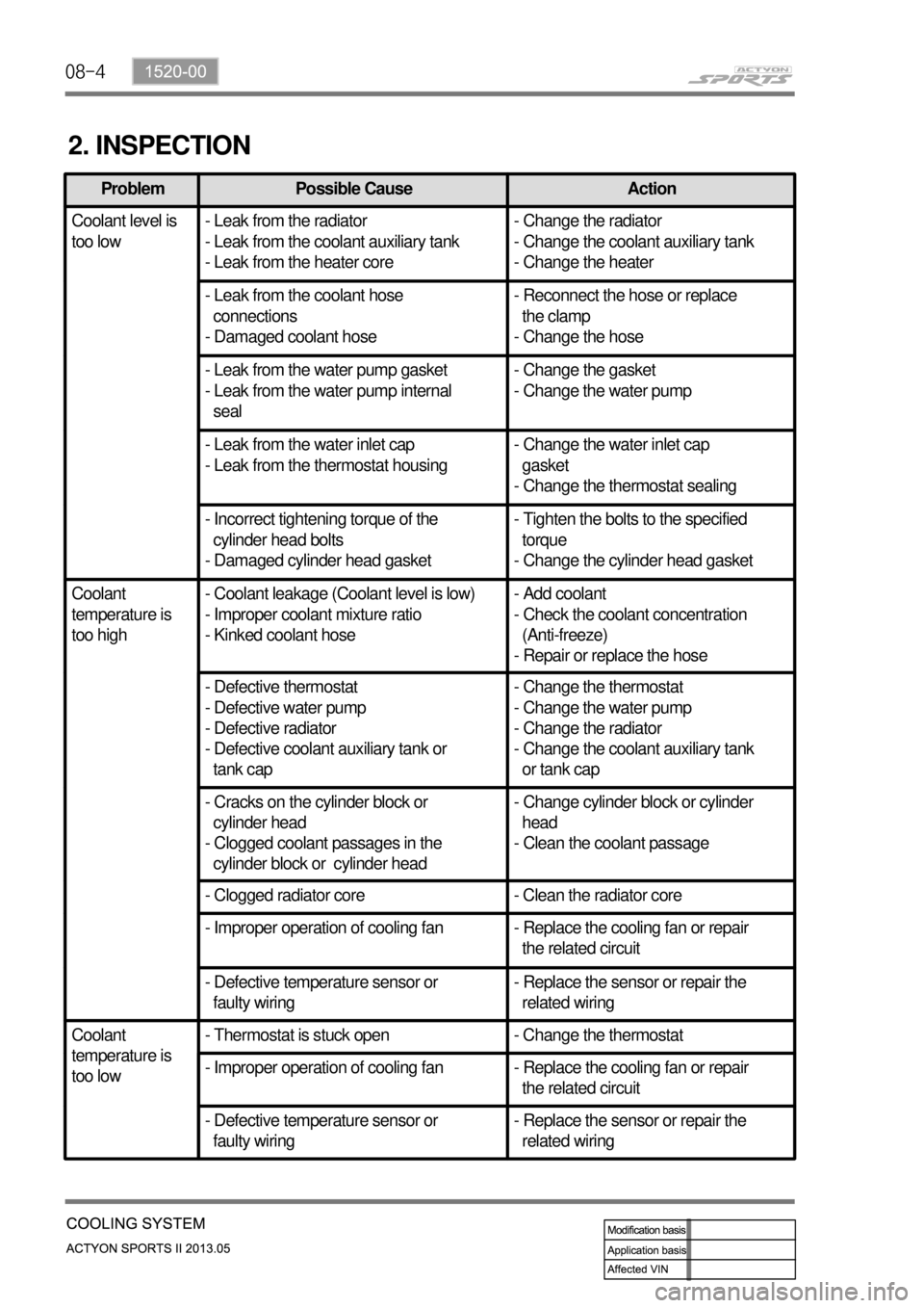
2. INSPECTION
Problem Possible Cause Action
Coolant level is
too low- Leak from the radiator
- Leak from the coolant auxiliary tank
- Leak from the heater core- Change the radiator
- Change the coolant auxiliary tank
- Change the heater
- Leak from the coolant hose
connections
- Damaged coolant hose- Reconnect the hose or replace
the clamp
- Change the hose
- Leak from the water pump gasket
- Leak from the water pump internal
seal- Change the gasket
- Change the water pump
- Leak from the water inlet cap
- Leak from the thermostat housing- Change the water inlet cap
gasket
- Change the thermostat sealing
- Incorrect tightening torque of the
cylinder head bolts
- Damaged cylinder head gasket- Tighten the bolts to the specified
torque
- Change the cylinder head gasket
Coolant
temperature is
too high- Coolant leakage (Coolant level is low)
- Improper coolant mixture ratio
- Kinked coolant hose- Add coolant
- Check the coolant concentration
(Anti-freeze)
- Repair or replace the hose
- Defective thermostat
- Defective water pump
- Defective radiator
- Defective coolant auxiliary tank or
tank cap- Change the thermostat
- Change the water pump
- Change the radiator
- Change the coolant auxiliary tank
or tank cap
- Cracks on the cylinder block or
cylinder head
- Clogged coolant passages in the
cylinder block or cylinder head- Change cylinder block or cylinder
head
- Clean the coolant passage
- Clogged radiator core - Clean the radiator core
- Improper operation of cooling fan - Replace the cooling fan or repair
the related circuit
- Defective temperature sensor or
faulty wiring- Replace the sensor or repair the
related wiring
Coolant
temperature is
too low- Thermostat is stuck open - Change the thermostat
- Improper operation of cooling fan - Replace the cooling fan or repair
the related circuit
- Defective temperature sensor or
faulty wiring- Replace the sensor or repair the
related wiring
Page 211 of 751

15-110000-00
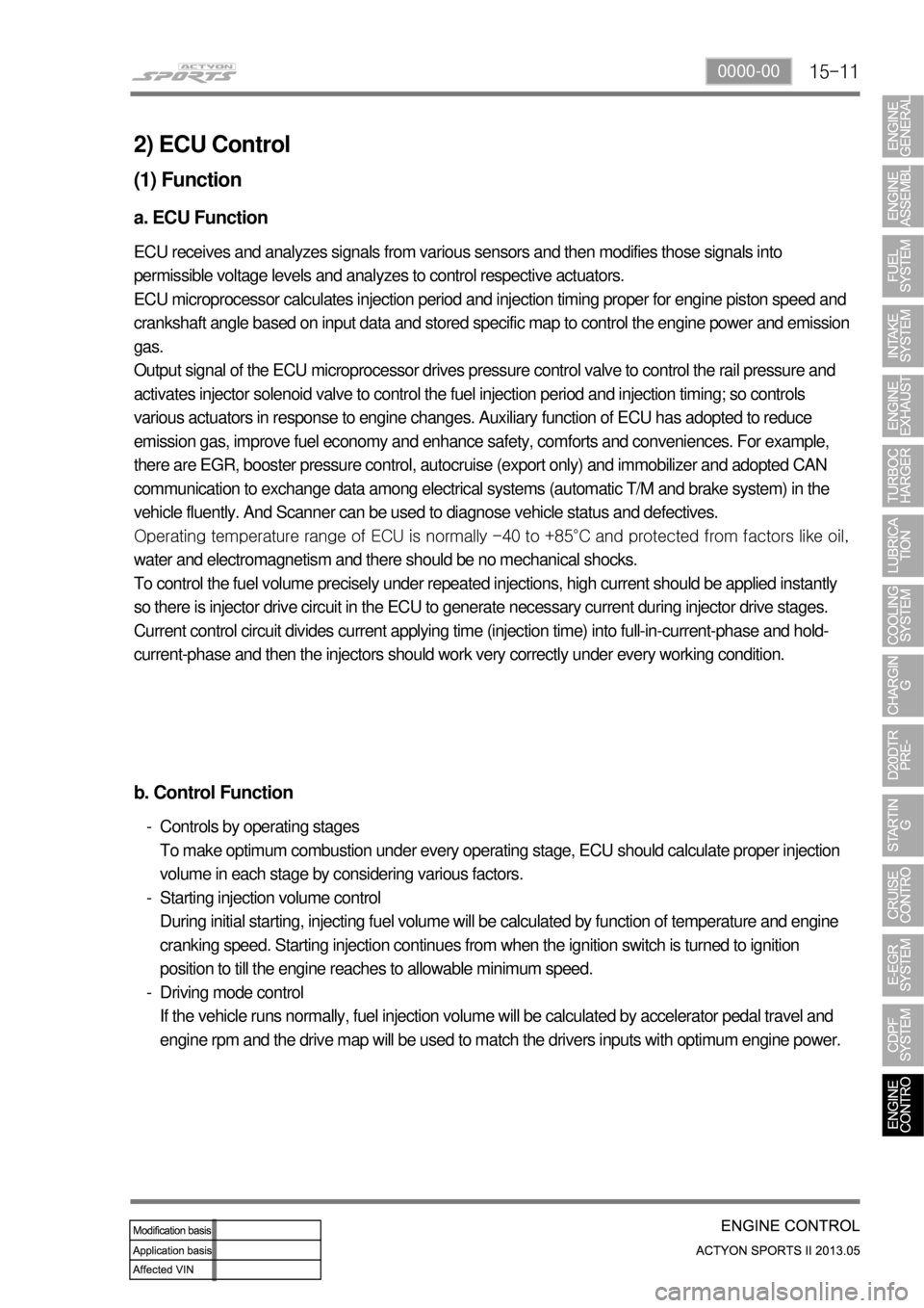
2) ECU Control
(1) Function
a. ECU Function
ECU receives and analyzes signals from various sensors and then modifies those signals into
permissible voltage levels and analyzes to control respective actuators.
ECU microprocessor calculates injection period and injection timing proper for engine piston speed and
crankshaft angle based on input data and stored specific map to control the engine power and emission
gas.
Output signal of the ECU microprocessor drives pressure control valve to control the rail pressure and
activates injector solenoid valve to control the fuel injection period and injection timing; so controls
various actuators in response to engine changes. Auxiliary function of ECU has adopted to reduce
emission gas, improve fuel economy and enhance safety, comforts and conveniences. For example,
there are EGR, booster pressure control, autocruise (export only) and immobilizer and adopted CAN
communication to exchange data among electrical systems (automatic T/M and brake system) in the
vehicle fluently. And Scanner can be used to diagnose vehicle status and defectives.
<00760097008c00990088009b00900095008e0047009b008c00940097008c00990088009b009c0099008c0047009900880095008e008c00470096008d0047006c006a007c00470090009a0047009500960099009400880093009300a000470054005b005700
47009b009600470052005f005c00b6006a004700880095008b> protected from factors like oil,
water and electromagnetism and there should be no mechanical shocks.
To control the fuel volume precisely under repeated injections, high current should be applied instantly
so there is injector drive circuit in the ECU to generate necessary current during injector drive stages.
Current control circuit divides current applying time (injection time) into full-in-current-phase and hold-
current-phase and then the injectors should work very correctly under every working condition.
b. Control Function
Controls by operating stages
To make optimum combustion under every operating stage, ECU should calculate proper injection
volume in each stage by considering various factors.
Starting injection volume control
During initial starting, injecting fuel volume will be calculated by function of temperature and engine
cranking speed. Starting injection continues from when the ignition switch is turned to ignition
position to till the engine reaches to allowable minimum speed.
Driving mode control
If the vehicle runs normally, fuel injection volume will be calculated by accelerator pedal travel and
engine rpm and the drive map will be used to match the drivers inputs with optimum engine power. -
-
-
Page 241 of 751

15-410000-00
D. Cooling fan and A/C compressor control
Conditions for cooling fan ▶
The cooling fan module controls the cooling fan relay, high speed relay and low speed relay. The cooling
fan is controlled by the series and parallel circuits.
A/C switch Cooling fanCoolant temperature Refrigerant pressure
A/C
compressor
OFF OFF Coolant temp. < 90℃ -
LO 90℃ ≤ Coolant temp.
< 105℃-
HI 105℃ ≤ Coolant temp. -
ONLO
Coolant temp. < 105℃Refrigerant pressure <
18 bar
ON
HI 18 bar ≤ Refrigerant
pressure
HI 105℃ ≤ Coolant temp.
< 115℃-
HI115℃ ≤ Coolant temp. -
OFF (cut)
A/C compressor OFF conditions ▶
Coolant temperature: below -20℃ or over
115℃
Approx. 4 seconds after starting the engine
Engine rpm: below 650 rpm or over 4500 rpm
When abrupt acceleration
Refrigerant pressure:
* OFF below 2.0 kg/㎠, then ON over 2.4 kg/㎠
* OFF over 30 kg/㎠, then ON below 21.4 kg/㎠ -
-
-
-
-
The output voltage from refrigerant pressure sensor is 1.7 V to 3.5 V when the refrigerant pressure is 10
to 24 kgf/㎠ with A/C "ON".Output voltage according to refrigerant pressure ▶
Cooling fan controls according to ATF ▶
ATF temperature Fan condition Remark
Over 110˚CHigh speed -
Page 244 of 751
15-44
D. Control conditions
Operation Operating condition PTC Heater
HI
(PTC2)- Coolant temperature < 15℃PTC HI ON
LO
(PTC1)- Coolant temperature 15℃ ≤ 65℃, intake air
temperature ≤ -10℃
- Coolant temperature 15℃ < 65 to 60℃, intake air
temperature <-10℃ to 0℃
- Coolant temperature 15℃ ≤ 60℃, intake air
temperature ≤ 0℃ to 5℃PTC LO ON
Stop- A/C blower switch OFF
- Defective ambient air temperature sensor
(including open or short circuit)
- Engine cranking
- Low battery voltage (below 11V)
- During pre-glow process (glow indicator ON)
Operation diagram for PTC heater LO (step 2) ▶
Page 302 of 751
01-38410-02
I/P - LH FUSE / RELAY BOX
- Power supply circuit for HFM sensor added (F30)
- Fuse for heated steering wheel added (F32)
1. MAJOR CHANGES
Driver’s interior fuse and relay box assembly changed ▶
F32
F30
Page 398 of 751
04-158210-01
4) Coolant Temperature Gauge
The coolant temperature gauge displays the coolant temperature with a pointer. The angle of pointer
that changes by coolant temperature is as shown below.
Measurement of coolant temperature sensor resistance
Measure the resistance between the terminal and the ground with an ohmmeter and replace if the
resistance is out of specified range.
Temperature (ºC)20 60 80 100 120
Resistance (Ω)2449Ω ± 5% 589.4kΩ ±
5%321Ω ± 5%185.7kΩ ±
5%112.9kΩ ±
5%
Voltage (V)3.615 1.910 1.259 0.819 0.536
When the resistance value by coolant temperature is within the specified range, check thermostat,
water pump, radiator related coolant circuit for normal operation. Also, check the wiring harnesses
and connectors for proper connection.
Page 439 of 751
09-58790-01
Parking Aid Unit
1. GENERAL INFORMATION
1) Components and Function
The parking aid system uses three piezoelectric
ceramic sensors inside the rear bumper to
measure the vertical and horizontal distances to
the obstacles. The parking aid system has a
separate unit that sends signal to the buzzer
when reverse parking to notify the driver of the
distance to obstacle. When placing the gear
selector lever to “R"
position, this unit activates
the sensor to measure the distance between the
object and the bumper. The existing PAS unit
displays the malfunctions using the LED when
there are any defects in sending/receiving signal
or the open circuit to sensor. On the other hand,
the PAS unit of KORANDO SPORTS informs the
malfunction of the relevant sensor using a
buzzer.
STICS
PAS buzzer
LH/RH sensor
Center sensor
Page 441 of 751
09-78790-01
When the ignition switch is in IGN1 position (shift
lever is in "R" position), the sensor will be
diagnosed once. If any malfunction due to an
open circuit in sensor or an error in
sending/receiving signals, the system warns the
driver with audible buzzer sound. If it is normal,
the warning buzzer sounds for 65 ms.
2) Troubleshooting
※ When the sensor failed in self-diagnostics
PAS buzzer
STICS