Page 629 of 751
11-274890-10
5) Hydraulic Circuit of HBA
The above figure shows one front and one rear wheel and the same hydraulic circuit forms as in the
ESP operation. When HECU recognizes that it is an emergency and it is required for hard braking,
depending on the pressure value of the brake pressure sensor and pressure changes caused by the
pressure sensor timing, it operates the pump immediately to apply the brake pressure at the wheels.
Then, the pressure in the pump increases until just before the corresponding wheel gets locked. The
motor still keeps rotating and the outlet valve and the separation valve will stay closed. When the wheel
starts to lock, the HBA function cancels and switches to ABS operation.
Page 689 of 751

01-10
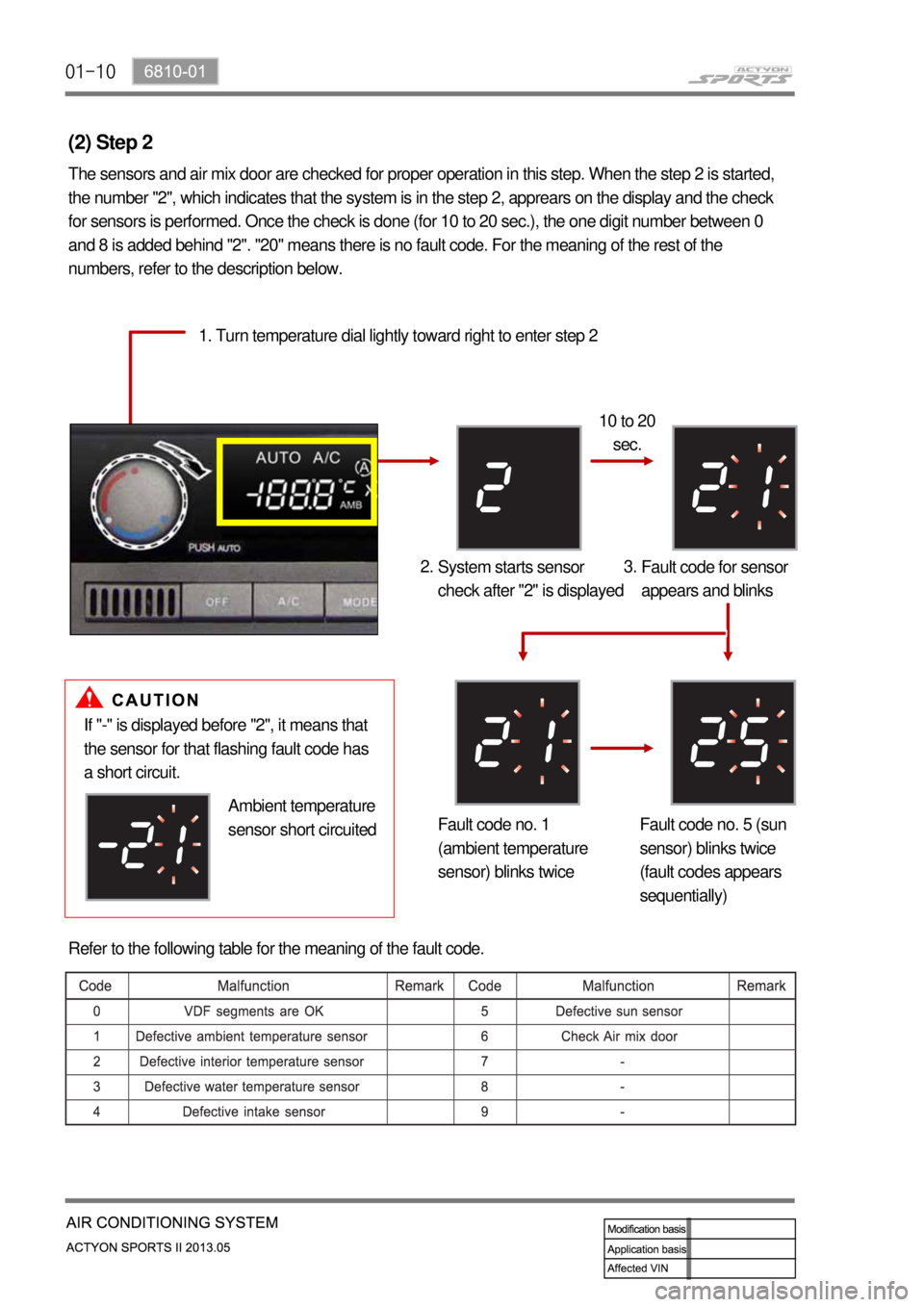
(2) Step 2
The sensors and air mix door are checked for proper operation in this step. When the step 2 is started,
the number "2", which indicates that the system is in the step 2, apprears on the display and the check
for sensors is performed. Once the check is done (for 10 to 20 sec.), the one digit number between 0
and 8 is added behind "2". "20" means there is no fault code. For the meaning of the rest of the
numbers, refer to the description below.
1. Turn temperature dial lightly toward right to enter step 2
10 to 20
sec.
System starts sensor
check after "2" is displayed 2.
Fault code for sensor
appears and blinks 3.
Fault code no. 1
(ambient temperature
sensor) blinks twiceFault code no. 5 (sun
sensor) blinks twice
(fault codes appears
sequentially)
If "-" is displayed before "2", it means that
the sensor for that flashing fault code has
a short circuit.
Ambient temperature
sensor short circuited
Refer to the following table for the meaning of the fault code.
Page 694 of 751

01-156810-01
3) Trouble Diagnosis
(1) Duct Temperature Sensor
If the fault code for the duct temperature sensor (DTC 3) appears on the display, check the sensor as
follows:
Remove the duct temperature sensor and measure the resistance between the terminals of the
<008a009600950095008c008a009b009600990047004f009a0097008c008a0090008d0090008a0088009b0090009600950061004700880097009700990096009f0055004700590055005900470092007e00470088009b00470059005c0b4500500055004700
70008d0047009b008f008c00470099008c009a0090009a009b>ance value is extremely high or
low, replace the duct temperature sensor.
If the result is not as specified, replace the duct temperature sensor. If the result is as specified,
proceed to the next step.
Turn the ignition switch to ON position and measure the voltage between the connector of the FATC
<008a00960095009b0099009600930093008c0099004700880095008b0047009b008f008c0047008b009c008a009b0047009b008c00940097008c00990088009b009c0099008c0047009a008c0095009a009600990047004f009a0097008c008a0090008d00
90008a0088009b009000960095006100470088009700970099>ox. 2 V at 25℃).
If the voltage cannot be measured, check the wiring for open circuit. If the result is as specified,
replace the FATC controller. A.
B.
C.
D.
(2) Power Transistor
If the fault code for the power transistor (DTC 6) is displayed, check as follows:
Turn the ignition switch to ON position.
Measure the voltage between the terminals of the blower motor while changing the fan speed from
the lowest level to the highest level.
The specified voltage value in each stage: A.
B.
C.
If the voltage is out of specified value, check the wiring for open circuit. If the wiring is intact, replace
the power transistor. D.
(3) Thermo AMP Sensor (Intake Air Sensor)
If the A/C is not turned on, check as follows:
Remove the thermo AMP and measure the voltage between the terminals no. 1 and 2 of the
connector.
Check if the voltage is approx. 12 V when the output is ON and 0 V when the output is OFF.
If the voltage value is not as specified, replace the thermo AMP. If the value is as specified, proceed
to the next step.
Turn the ignition switch to ON position and turn on the A/C by pressing the A/C button. And measure
the voltage between the terminals A12 and A11 of the FATC controller connector (specification:
approx. 12 V).
If the voltage cannot be measured, check the wiring for open circuit. If the result is not as specified,
replace the thermo AMP. A.
B.
C.
D.
E.
Page 695 of 751
01-16
(4) Sun-load sensor
Remove the sun-load sensor and measure the current between the terminals with the sensor
exposed to direct sunlight.
Measure the current again in the shade. If this value is lower than the measured value in the
sunlight, the sensor is intact.
Turn the ignition switch to the "ON" position.
Measure the voltage between the terminals of the sun sensor at the FATC connector. (approx. 2.5 V
under sunlight and approx. 4.8 V under shade)
If the voltage cannot be measured, check the wiring for open circuit. If the result is not as specified,
replace the FATC controller. A.
B.
C.
D.
E.
Page 706 of 751
01-276810-01
7. FATC (FULL AUTO TEMP. CONTROL) CIRCUIT
1) PWM Motor, Compressor, Air Mix Motor, Sun Sensor