Page 54 of 751
02-230000-00
2) Oil Separator
Oil separator separates the particle in blow-by gas to minimize the engine oil consumption and reduces
the inflow oil from intake system into the combustion chamber. The separated oil returns to oil pan
through cylinder head.
Oil separator
Blow-by outlet hose
(1) Overview
(2) Layout
Page 57 of 751
02-26
Intake/Exhaust Camshafts
2) Camshaft
(1) Overview
Hollow type camshaft contains cam, octagon cam, HP pump gear and intake/\
exhaust gears.
Camshaft operates the intake/exhaust valves, vacuum pump and HP pump, an\
d transfers the engine
oil to vacuum pump through the internal oil passage.
(2) Location
Exhaust CamshaftHP Pump Gear
Octagon cam
(for tooling)
Thrust journal
Connected to
vacuum pumpIntake Camshaft
Cross flow type water jacket (improving cooling performance)
▶
Page 60 of 751

02-290000-00
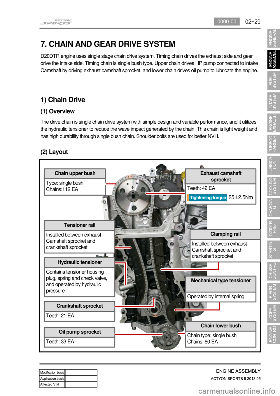
(2) Layout
Chain upper bush
Type: single bush
Chains:112 EA
Tensioner rail
Installed between exhaust
Camshaft sprocket and
crankshaft sprocket
Hydraulic tensioner
Contains tensioner housing
plug, spring and check valve,
and operated by hydraulic
pressure
Crankshaft sprocket
Teeth: 21 EA
Oil pump sprocket
Teeth: 33 EA
Chain lower bush
Chain type: single bush
Chains: 60 EA
Mechanical type tensioner
Operated by internal spring
Clamping rail
Installed between exhaust
Camshaft sprocket and
crankshaft sprocket
Exhaust camshaft sprocket
Teeth: 42 EA
1) Chain Drive
(1) Overview
The drive chain is single chain drive system with simple design and variable performance, and it utilizes
the hydraulic tensioner to reduce the wave impact generated by the chain\
. This chain is light weight and
has high durability through single bush chain. Shoulder bolts are used f\
or better NVH.
7. CHAIN AND GEAR DRIVE SYSTEM
D20DTR engine uses single stage chain drive system. Timing chain drives the exhaust side and gear
drive the intake side. Timing chain is single bush ty pe. Upper chain drives HP pump connected to intake
Camshaft by driving exhaust camshaft sprocket, and lowe r chain drives oil pump to lubricate the engine.
25±2.5Nm
Page 65 of 751
02-34
Oil pan sassembly
8. OIL PAN
The oil pan in D20DTR engine improves the NVH. Especially, the oil draining is much easier than before.
Components ▶
Page 70 of 751
02-390000-00
1) Piston
(1) Overview
Piston assembly contains piston, #1 ring, #2
ring, oil ring, piston pin and snap ring. The
expansion energy from engine is transferred to
the crankshaft through connecting rod to convert
the linear movement to rotating energy.
(2) Layout
#1 ring
Oil ring
Snap ring
#2 ringMaterial: B2+
Skirt coating:
MoS2
Piston cooling gallery for
connecting rod
Wide bowl type (CR 16.5)
Cooling jet
Page 71 of 751

02-40
(3) Functions
Piston transfers the combustion energy from engine to connecting rod. Es\
pecially in the direct injection
engine such as D20DTR, it provides the combustion space and largely effects to the engine performance
and exhaust gas.
Piston ring
#1 ring (Top ring) : Prevents the high pressurized combustion gas from leaking into crank chamber,
and prevents the engine oil getting into combustion chamber.
#2 ring: Scrapes the engine oil on the cylinder bore, and prevents the leaked combustion gas from #1
ring from leaking into the crank chamber.
Oil ring: Scrapes the engine oil on the cylinder bore.
Piston pin
Connects the piston the connecting rod, and transfers the linear movemen\
t of piston to connecting rod
to convert it to rotating energy
Snap ring
Locks the piston pin.
▶
-
-
-
▶ -
▶ -
(4) Assembling the piston
Install the piston rings with the "Y" mark on the
ring facing upwards.
Position the end gap of #1 ring at 180˚
away from the end gap of #1 ring.
Position the end gap of oil ring at 180˚
away from the end gap of coil spring, and
position the end gap of oil ring at 90˚ away
from the end gap of #2 ring.
1.
2.
3.
Page 79 of 751
02-48
The bottom side of water jacket is desgined as sine wave to strengthen the structure of crankcase. The
main flow of coolant starts from outlet port of water pump and goes along the longitudinal direction of
engine. The coolant passage from cylinder head to inlet port of water pump is integrated in cylinder head.
The engine oil from oil pump is supplied to the main oil gallery through oil channel, oil filter module and
cross bore in cylinder block without using external pipes. This oil is supplied to main bearing, cylinder
head and MBU. And, it is sprayed to the chain through the chain tensioner connected to cross bore.
Crankcase cross bore for oil supply
Water jacket core
Page 81 of 751
03-4
2. MAINTENANCE AND INSPECTION
1) Maintenance Procedures for DI Engine Fuel System
Always keep the workshop and lift clean (especially, from dust).
Always keep the tools clean (from oil or foreign materials).
Wear a clean vinyl apron to prevent the fuzz, dust and foreign materials from getting into fuel system.
Wash your hands and do not wear working gloves. 1.
2.
3.
Follow the below procedures before starting service works for fuel system.
If the problem is from HP pump, fuel supply line or injector, prepare the clean special tools and sealing
caps to perform the diagnosis for DI engine fuel system in this manual. At this point, thoroughly clean
the related area in engine compartment. 4.
Clean the engine compartment before starting service works.
Tool kit for high pressure lineTook kit for low pressure line