Page 622 of 751

11-20
5) ARP (Active Roll-Over Protection
The ARP (Active Roll-over Protection) system is a safety assistant device that minimizes, by controlling
brakes and the engine, the physical tendency of the vehicle rollover during sharp lane changes or U-
turns. For the system, software is added to the existing ESP system and no additional device or switch is
needed. One must note that the ARP system, just as general assistant devices including the ABS, is only
a safety assistant device using the ESP system and its function is useless when the situation overcomes
the physical power. Following picture shows how the ARP compensates the vehicle position by varying
each wheel's braking power to overcome the physical tendency of the vehicle rollover during sharp turns.
Lateral sensor
(In sensor cluster)
Vehicle speedBrake force
Radius
The vehicle driving condition is controlled by the internally programmed logic according to the input
signals from wheel speed sensor, steering angle sensor and lateral sensor.
During the ARP operation, vehicle safety (rollover prevention) takes the first priority and thus, stronger
engine control is in effect. Consequently, the vehicle speed decreases rapidly, so the driver must take
caution for the vehicle may drift away from the lane.
Page 624 of 751

11-22
Circuit description ▶
When compared to the vehicle equipped with ABS/EBD only, the internal hydraulic circuit has a
normally-open separation valve and a shuttle valve in primary circuit and in secondary circuit.
When the vehicle brakes are not applied during engine running or when applying the non-ABS operating
brakes, the normally-open separation valve and the inlet valve are open, whereas the normally-closed
shuttle valve and the outlet valve are closed.
When the ESP system is operating, the normally-open separation valve will be closed by the solenoid
valve operation and the hydraulic circuit will be established by the shuttle valve. Then, the inlet and outlet
valves will be closed or open depending on the braking pressure RISE, HOLD or DUMP conditions.
Flashing warning lamp and warning sound during ESP operation ▶
When the ESP operates while the vehicle is moving, the ESP warning lamp on the instrument panel
flickers and the buzzer sounds at every 0.1 second. The ESP lamp operation is to inform a driver that the
vehicle is extremely unstable.
The ESP system is just a supplementary system for the vehicle and it cannot control the vehicle over the
physical limit. Do not solely rely on the system but be advised to drive the vehicle safely.
Drive feeling during ESP operation ▶
When the ESP system activates, the driving feeling can be different depending on vehicle driving
conditions. For example, it will feel different when the ESP system is activated while the ABS is operated
by depressing the brake pedal and when the ESP system is in control without the brake pedal
depressed on the same curve.
If the ESP system operates with the brake applied, the brake pressure will be increased on the
corresponding wheel which already has braking pressure for the ESP controls. In other words, the ESP
system would make the driver feel more abruptly braked compared to the situation that the braking
pressure is applied to wheel which had no braking force.
Noise and vibration that driver senses during ESP operation ▶
The ESP system may transfer noise and vibration to a driver due to the pressure changes caused by the
motor and valve operations in a very short period of time.
Extreme cornering will trigger the ESP operation and this will make the driver sense noise and vibration
due to sudden brake application.
Also, the ESP system controls the engine power. Therefore, the driver may notice the engine power
decreases even when the accelerator pedal is depressed.
Page 625 of 751
11-234890-10
1) Idling and Normal Braking Condition
In this position, the separation valve and the inlet valve are open (normal open), the electrically operated
shuttle valve and the outlet valve are closed.
When the brake is applied under these conditions, the brake fluid will be sent to each wheel via the
separation valve and inlet valve.
Page 629 of 751
11-274890-10
5) Hydraulic Circuit of HBA
The above figure shows one front and one rear wheel and the same hydraulic circuit forms as in the
ESP operation. When HECU recognizes that it is an emergency and it is required for hard braking,
depending on the pressure value of the brake pressure sensor and pressure changes caused by the
pressure sensor timing, it operates the pump immediately to apply the brake pressure at the wheels.
Then, the pressure in the pump increases until just before the corresponding wheel gets locked. The
motor still keeps rotating and the outlet valve and the separation valve will stay closed. When the wheel
starts to lock, the HBA function cancels and switches to ABS operation.
Page 642 of 751

12-134610-01
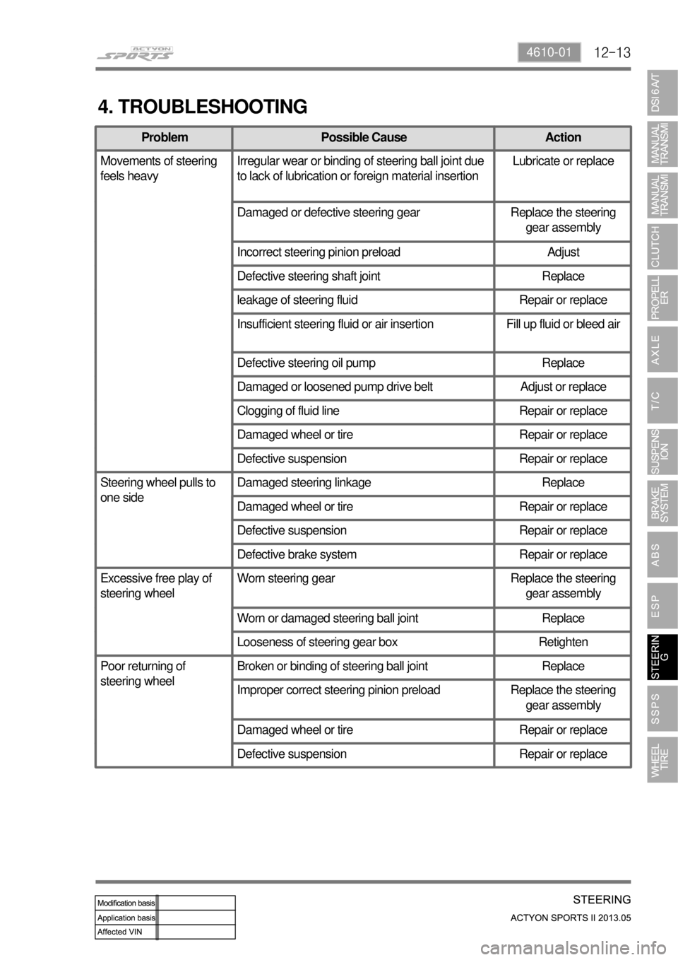
4. TROUBLESHOOTING
Problem Possible Cause Action
Movements of steering
feels heavyIrregular wear or binding of steering ball joint due
to lack of lubrication or foreign material insertionLubricate or replace
Damaged or defective steering gear Replace the steering
gear assembly
Incorrect steering pinion preload Adjust
Defective steering shaft joint Replace
leakage of steering fluid Repair or replace
Insufficient steering fluid or air insertion Fill up fluid or bleed air
Defective steering oil pump Replace
Damaged or loosened pump drive belt Adjust or replace
Clogging of fluid line Repair or replace
Damaged wheel or tire Repair or replace
Defective suspension Repair or replace
Steering wheel pulls to
one sideDamaged steering linkage Replace
Damaged wheel or tire Repair or replace
Defective suspension Repair or replace
Defective brake system Repair or replace
Excessive free play of
steering wheelWorn steering gear Replace the steering
gear assembly
Worn or damaged steering ball joint Replace
Looseness of steering gear box Retighten
Poor returning of
steering wheelBroken or binding of steering ball joint Replace
Improper correct steering pinion preload Replace the steering
gear assembly
Damaged wheel or tire Repair or replace
Defective suspension Repair or replace
Page 648 of 751
12-194610-01
Oil Pump Pressure Check ▶
Unscrew the pressure line fitting in power
steering pump.
Install the pressure gauge between the
power steering pump and the power steering
oil pressure line.
Place the shift lever to neutral position. Apply
the parking brake.
Open the valve in pressure gauge. Start the
engine and let it run at idle speed.
Turn the steering wheel several times so that
the oil temperature reaches to normal
operating level. 1.
2.
3.
4.
5.
Before checking the pressure, check the oil
level and belt tension. Prepare the empty
container to collect the spilled oil during the
service. Check the oil pump pressure to locate any
defect in oil pump.
Fully close the valve in pressure gauge and
measure the oil pressure. 6.
Relief pressure
90 ± 3 bar
Oil pump
Steering gear box
To prevent internal damage, do not close
the gauge valve over 10 seconds.
Keep the oil temperature at proper range. -
-
Page 665 of 751
14-4
3. TROUBLE DIAGNOSIS
Problem Possible Cause Action
Uneven tire wear Incorrect tire pressure Adjust
Unbalanced wheel Adjust
Improper location change of tire Change tire location in
specified interval
Incorrect toe adjustmen Adjust
Incorrect wheel bearing preload adjustment Adjust
Malfunction of brake syste Adjust
Tire squeal, vibration Too low tire pressure Adjust
Unbalanced wheel or tire Adjust
Heavy vibration of wheel or tire Uneven tire wear
Uneven tire wear Check and adjust
Premature tire wear Too high tire pressure Adjust
Fast driving with low pressure tire Adjust
Overload Adjust
Page 668 of 751

14-74170-09
2) Typical Inspection
Tread
Inspect the tread condition on the tire surface
and various damages resulting from the
foreign materials, crack, stone or nail etc. If
there is any damage in the tire, repair or
replace it. 1.
Wear limit 2.
Measure the depth of the tire tread. If the
depth of the tread is below the specified
value, replace the tire -
You can see the protruded part in the
groove at the point with mark "▲", which
is the indicator of the tread wear limit.
The limit of the tread wear for all season
tires are 1.6 mm, which is the same as the
general tires, but the wear limit mark is
indicated as '↓'. -
-
Wear limit 1.6 mm
Higher than recommended pressure can cause hard ride, tire bruising or damage and rapid tread
wear at the center of the tire.
Excessive tire wear over the limit of the tread wear (1.6 mm) can cause lower sliding friction due to
longer braking distance, easy tire burst by foreign materials, tire hydroplaning, and tough brake and
steering wheel handling. -
-