Page 1031 of 1336
3660-01
The shiftable gear can be adjusted by pressing the
"UP (D+)" or "DOWN(D-)" switch when the gear
Shift lock release button
If the selector lever cannot be moved from
while pushing down this button with finger. For
safety, turn off the engine and depress the
brake pedal before the attempt.Shift up Shift down Tip switches on steering wheel
Meter cluster
This indicator shows the current position of
the gear.
Gear selector lever
Lever positions
P : Park
R : reverse
N : Neutral
D : DriveTip switch (manual shift switch)
The shiftable gear can be adjusted by
moving this switch to forward and rearward
position.
Selection of Manual/Automatic Shift Function
D: Automatic shift according to the driving condition
M: Manual shift
Page 1032 of 1336
3. SPECIFICATIONS
1) Specifications
Type/Weight 6F24 6-speed automatic transaxle /
approx. 86 kg (including ATF)
TORQUE 230 Nm
Overall length / Center length 373.1 mm / 204 mm
Descriptions Specification
Gear ratio 1st gear 4.212
2nd gear 2.637
3rd gear 1.800
4th gear 1.386
5th gear 1.000
6th gear 0.772
Reverse gear 3.385
Shift pattern Variable
Shift range 4 Range (P-R-N-D) + Manual mode
Shift range valve VFS : 6EA
Planetary gear 3EA (Front, Middle, Rear)
Clutch 2EA
Brake 3EA
O.W.C 1EA
Oil Type ATF SP-IV M
Capacity approx. 7.1 L
Change interval Maintenance free. However, under the severe
conditions or commercially used, change the oil at
every 100,000 km (EU: 90,000 km).
Resistance of oil
temperature sensor-20
0
20
100
Weight 2WD 87.5kg
4WD 88.5kg
Page 1035 of 1336
3660-01
DescriptionsSize x
NumbersTightening torque
(Nm)
Automatic
transaxleBolt (oil lubrication pipe) 10 mm X 1 9.8 ~ 11.7Nm
Bolt (oil pump) 12 mm X 7 20.0 ~ 26.0Nm
Bolt (parking rod guide) 10 mm X 2 9.8 ~ 11.7Nm
Bolt (U/D brake retainer) T40 X 6 31.0 ~ 36.0Nm
Bolt (U/D brake chamber) T30 X 2 4.9 ~ 9.8Nm
Bolt (rear cover) 12 mm X 13 28.0 ~ 35.0Nm
Page 1036 of 1336
6. SPECIAL SERVICE TOLLS
Part number Name Tool How to use
00104-001(UD) Remover &
Installer - U/D
brake return sprin
00104-002(OD) Remover&
Installer - O/D
clutch return
spring
00104-003(LR)
(use with 00104-001)Remover&
Installer - L/R
brake return
spring
* Special service tool Supplier: Tool & Tech
Page 1037 of 1336

3660-01
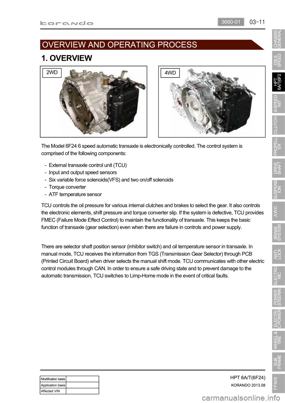
1. OVERVIEW
2WD4WD
The Model 6F24 6 speed automatic transaxle is electronically controlled. The control system is
comprised of the following components:
External transaxle control unit (TCU)
Input and output speed sensors
Six variable force solenoids(VFS) and two on/off solenoids
Torque converter
ATF temperature sensor -
-
-
-
-
TCU controls the oil pressure for various internal clutches and brakes to select the gear. It also controls
the electronic elements, shift pressure and torque converter slip. If the system is defective, TCU provides
FMEC (Failure Mode Effect Control) to maintain the functionality of transaxle. This keeps the basic
function of transaxle (gear selection) even when there are failure in controls and power supply.
There are selector shaft position sensor (inhibitor switch) and oil temperature sensor in transaxle. In
manual mode, TCU receives the information from TGS (Transmission Gear Selector) through PCB
(Printed Circuit Board) when driver selects the manual shift mode. TCU communicates with other electric
control modules through CAN. In order to ensure a safe driving state and to prevent damage to the
automatic transmission, TCU switches to Limp-Home mode in the event of critical faults.
Page 1043 of 1336

3660-01
5. TRANSAXLE ELECTRONIC CONTROL SYSTEM
1) General Information
The transmission control unit (TCU) and its input/output network control the following transmission
operations:
Shift timing
Line pressure
Clutch pressure (shift feel)
Torque converter clutch -
-
-
-
also uses these signals when determining transaxle operating strategy. Using all of these input signals,
the TCU can determine when the time and conditions are right for a shift, or when to apply or release the
torque converter clutch. It will also determine the pressure needed to optimise shift feel.
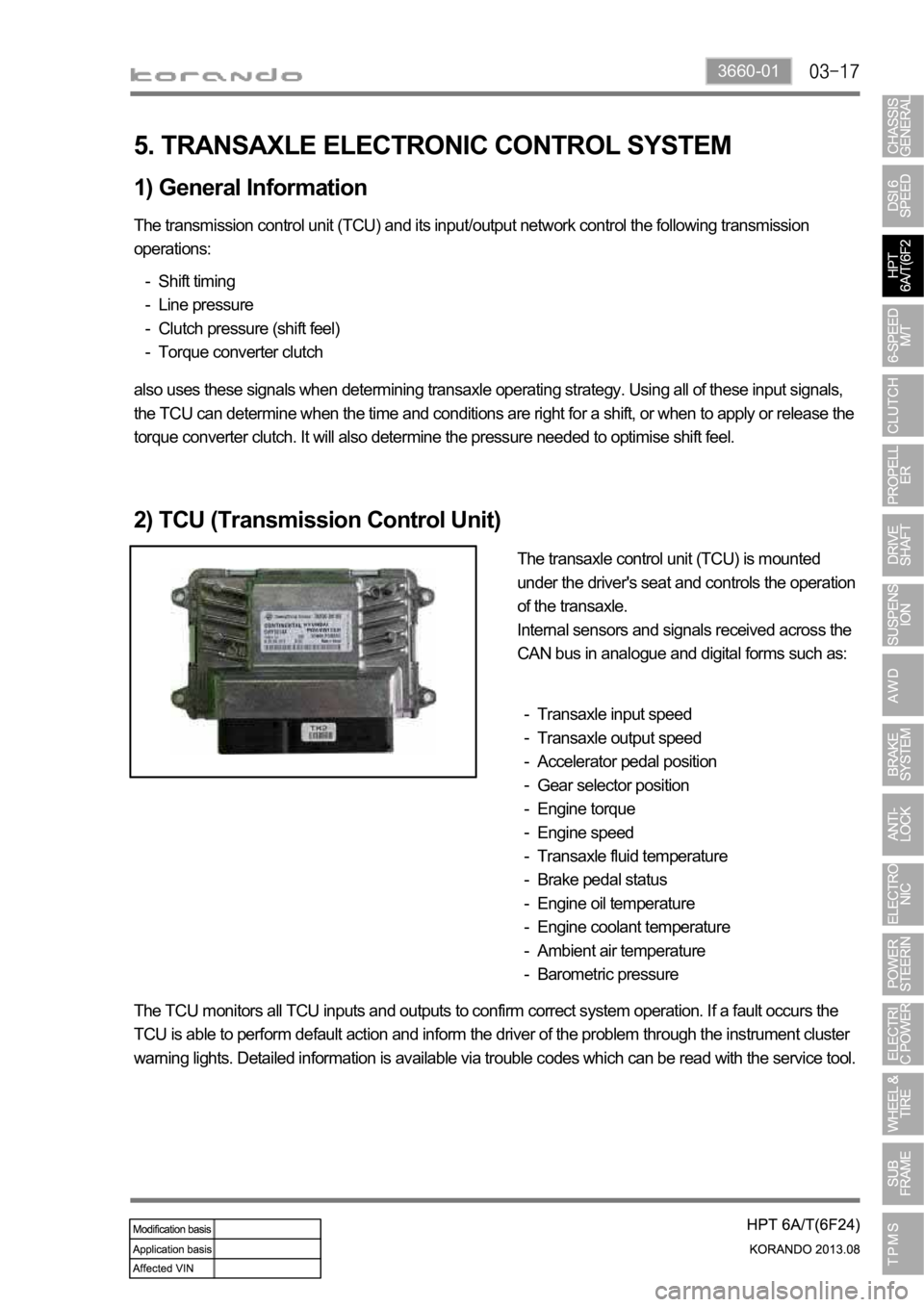
2) TCU (Transmission Control Unit)
The transaxle control unit (TCU) is mounted
under the driver's seat and controls the operation
of the transaxle.
Internal sensors and signals received across the
CAN bus in analogue and digital forms such as:
Transaxle input speed
Transaxle output speed
Accelerator pedal position
Gear selector position
Engine torque
Engine speed
Transaxle fluid temperature
Brake pedal status
Engine oil temperature
Engine coolant temperature
Ambient air temperature
Barometric pressure -
-
-
-
-
-
-
-
-
-
-
-
The TCU monitors all TCU inputs and outputs to confirm correct system operation. If a fault occurs the
TCU is able to perform default action and inform the driver of the problem through the instrument cluster
warning lights. Detailed information is available via trouble codes which can be read with the service tool.
Page 1045 of 1336
3660-01
7. POWER TRANSFER
Power transfer modes are as follow:
Manual: 1st gear (position M)
Drive: 1st gear
Drive: 2nd gear
Drive: 3rd gear
Drive: 4th gear - limp home mode
Drive: 5th gear
Drive: 6th gear -
-
-
-
-
-
-
1) Overview
Name Component
C1 OVER DRIVE CLUTCH
C2 35R CLUTCH
B1 LOW & REVERSE BRAKE
B2 2/6 BRAKE
B3 UNDER DRIVE BRAKE
1F 1-2 ONE WAY CLUTCH
GEARCLUTCH BRAKE
OWC Gear Ratio
OD 35R 26 LR UD
1ST
O O 4.212
2ND O O 2.637
3RD O O 1.800
4TH O O 1.386
5TH O O 1.000
6TH O O 0.772
REV O O 3.385
N.P O
(1) Gear Selection and Engagement Element
Operation when vehicle speed under 5kph *
Page 1088 of 1336
4850-00
1. SYSTEM OVERVIEW
1) Terms and Definition
CBS: Conventional Brake System
ABS: Anti-Lock Brake System
EBD: Electronic brake-Force Distribution
ESP: Electronic Stability Program
ABD: Automatic Braking Differential
ASR: Acceleration Slip Regulation
AYC: Active Yaw Control (Understeer and Oversteer Control)
HBA: Hydraulic Brake Assistant
ARP: Active Rollover Protection
HSA: Hill Start Assistant -
-
-
-
-
-
-
-
-
-
2) Functions
FunctionVehicle with CBS
Vehicle with ABS/EBD Vehicle with ESP
ABS
Not appliedApplied
Applied EBD Applied
ABD
Not applied ASR
AYC
HBA
ARP
HSA