Page 1130 of 1336
0000-00
3) Vehicle Control During Cornering
The figure below shows the vehicle controls by the ESP system under various situations such as when
the brake pedal is depressed or not depressed during cornering, when the ABS is operating and when
braking without the ABS. It also includes the vehicle conditions when the TCS, a part of the ESP system,
is operating.
Condition Understeer control Oversteer control
Only ESP in
operation
No braking by driver
ESP
+
Normal braking
(no ABS operation)
ESP
+
ABS brake
ESP + ASR
Page 1131 of 1336

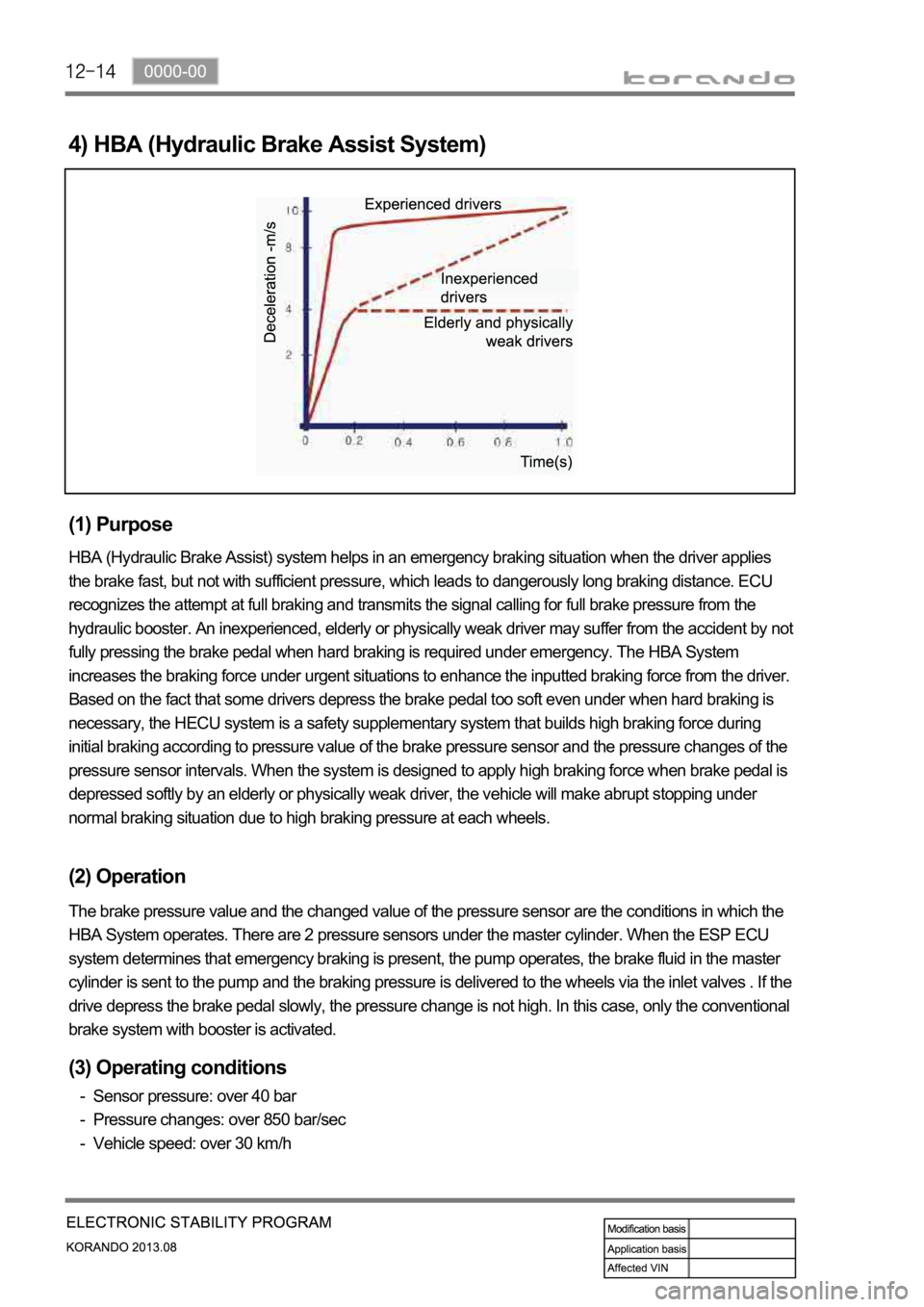
4) HBA (Hydraulic Brake Assist System)
(1) Purpose
HBA (Hydraulic Brake Assist) system helps in an emergency braking situation when the driver applies
the brake fast, but not with sufficient pressure, which leads to dangerously long braking distance. ECU
recognizes the attempt at full braking and transmits the signal calling for full brake pressure from the
hydraulic booster. An inexperienced, elderly or physically weak driver may suffer from the accident by not
fully pressing the brake pedal when hard braking is required under emergency. The HBA System
increases the braking force under urgent situations to enhance the inputted braking force from the driver.
Based on the fact that some drivers depress the brake pedal too soft even under when hard braking is
necessary, the HECU system is a safety supplementary system that builds high braking force during
initial braking according to pressure value of the brake pressure sensor and the pressure changes of the
pressure sensor intervals. When the system is designed to apply high braking force when brake pedal is
depressed softly by an elderly or physically weak driver, the vehicle will make abrupt stopping under
normal braking situation due to high braking pressure at each wheels.
(2) Operation
The brake pressure value and the changed value of the pressure sensor are the conditions in which the
HBA System operates. There are 2 pressure sensors under the master cylinder. When the ESP ECU
system determines that emergency braking is present, the pump operates, the brake fluid in the master
cylinder is sent to the pump and the braking pressure is delivered to the wheels via the inlet valves . If the
drive depress the brake pedal slowly, the pressure change is not high. In this case, only the conventional
brake system with booster is activated.
(3) Operating conditions
Sensor pressure: over 40 bar
Pressure changes: over 850 bar/sec
Vehicle speed: over 30 km/h -
-
-
Page 1132 of 1336

0000-00
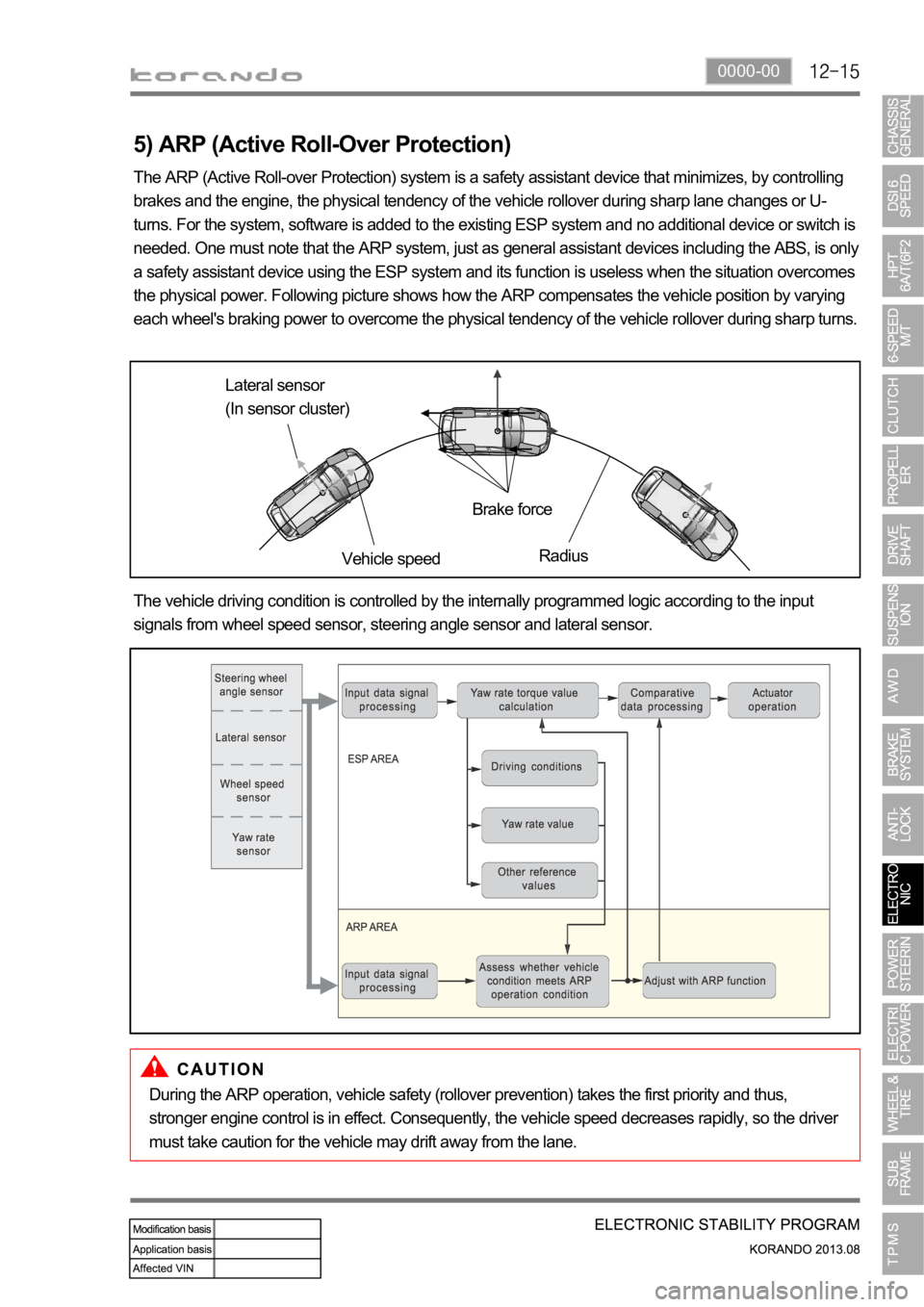
5) ARP (Active Roll-Over Protection)
The ARP (Active Roll-over Protection) system is a safety assistant device that minimizes, by controlling
brakes and the engine, the physical tendency of the vehicle rollover during sharp lane changes or U-
turns. For the system, software is added to the existing ESP system and no additional device or switch is
needed. One must note that the ARP system, just as general assistant devices including the ABS, is only
a safety assistant device using the ESP system and its function is useless when the situation overcomes
the physical power. Following picture shows how the ARP compensates the vehicle position by varying
each wheel's braking power to overcome the physical tendency of the vehicle rollover during sharp turns.
Lateral sensor
(In sensor cluster)
Vehicle speedBrake force
Radius
The vehicle driving condition is controlled by the internally programmed logic according to the input
signals from wheel speed sensor, steering angle sensor and lateral sensor.
During the ARP operation, vehicle safety (rollover prevention) takes the first priority and thus,
stronger engine control is in effect. Consequently, the vehicle speed decreases rapidly, so the driver
must take caution for the vehicle may drift away from the lane.
Page 1133 of 1336
6) HSA (Hill Start Assist)
The HSA (Hill Start Assist) prevents the vehicle from rolling backward by supplying the hydraulic
pressure to the wheels by the HECU after the brake pedal is released when starting off on uphill.
Page 1137 of 1336

Circuit description
When compared to the vehicle equipped with ABS/EBD only, the internal hydraulic circuit has a
normally-open separation valve and a shuttle valve in primary circuit and in secondary circuit.
When the vehicle brakes are not applied during engine running or when applying the non-ABS operating
brakes, the normally-open separation valve and the inlet valve are open, whereas the normally-closed
shuttle valve and the outlet valve are closed.
When the ESP system is operating, the normally-open separation valve will be closed by the solenoid
valve operation and the hydraulic circuit will be established by the shuttle valve. Then, the inlet and outlet
valves will be closed or open depending on the braking pressure RISE, HOLD or DUMP conditions.
Flashing warning lamp and warning sound during ESP operation
When the ESP operates while the vehicle is moving, the ESP warning lamp on the instrument panel
flickers and the buzzer sounds at every 0.1 second. The ESP lamp operation is to inform a driver that the
vehicle is extremely unstable.
The ESP system is just a supplementary system for the vehicle and it cannot control the vehicle over the
physical limit. Do not solely rely on the system but be advised to drive the vehicle safely.
Drive feeling during ESP operation
When the ESP system activates, the driving feeling can be different depending on vehicle driving
conditions. For example, it will feel different when the ESP system is activated while the ABS is operated
by depressing the brake pedal and when the ESP system is in control without the brake pedal
depressed on the same curve.
If the ESP system operates with the brake applied, the brake pressure will be increased on the
corresponding wheel which already has braking pressure for the ESP controls. In other words, the ESP
system would make the driver feel more abruptly braked compared to the situation that the braking
pressure is applied to wheel which had no braking force.
Noise and vibration that driver senses during ESP operation
The ESP system may transfer noise and vibration to a driver due to the pressure changes caused by the
motor and valve operations in a very short period of time.
Extreme cornering will trigger the ESP operation and this will make the driver sense noise and vibration
due to sudden brake application.
Also, the ESP system controls the engine power. Therefore, the driver may notice the engine power
decreases even when the accelerator pedal is depressed.
Page 1138 of 1336
0000-00
1) Idling and Normal Braking Condition
In this position, the separation valve and the inlet valve are open (normal open), the electrically operated
shuttle valve and the outlet valve are closed.
When the brake is applied under these conditions, the brake fluid will be sent to each wheel via the
separation valve and inlet valve.
Page 1142 of 1336
0000-00
5) Hydraulic Circuit of HBA
The above figure shows one front and one rear wheel and the same hydraulic circuit forms as in the ESP
operation. When HECU recognizes that it is an emergency and it is required for hard braking, depending
on the pressure value of the brake pressure sensor and pressure changes caused by the pressure sensor
timing, it operates the pump immediately to apply the brake pressure at the wheels. Then, the pressure in
the pump increases until just before the corresponding wheel gets locked. The motor still keeps rotating
and the outlet valve and the separation valve will stay closed. When the wheel starts to lock, the HBA
function cancels and switches to ABS operation.
Page 1158 of 1336

1. OVERVIEW
A radial tire uses a cord angle of 90 degrees. That is, the cord material runs in a radial or direct line from
one bead to the other across the tread. In addition, a radial tire has a belt overwrap under the tread
surface to provide greater structural stability. The belt overwrap of a radial tire distortion while the radial
structure enables high speed driving.
Tire supports the weight of the vehicle, reduces the impact from the road and at the same time,
transmits the power to propel, brake and steer on the road. It also functions to maintain a
vessel of air.
There is wear limit mark on the tire, which protrudes as a strip shape located approximately 1.6 mm from
mark on the shoulder to let the driver find the wear mark easily. To measure the tire groove depth,
measure at any point other than the point which has a wear limit mark.
The tire is worn unevenly according to the driver's driving habit, improper servicing, low tire inflation
pressure, changed tire location, etc.
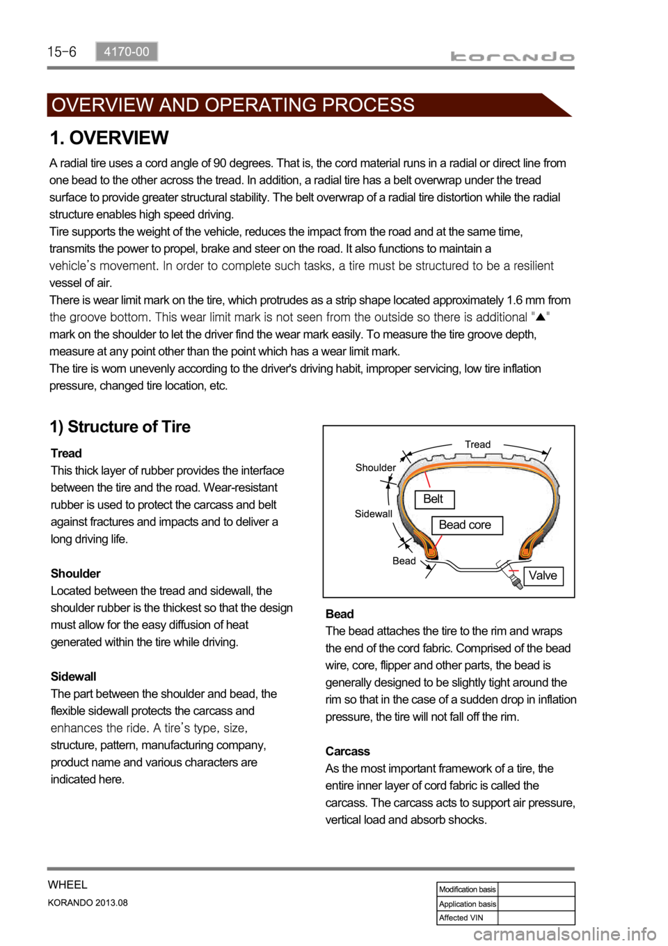
1) Structure of Tire
Tread
This thick layer of rubber provides the interface
between the tire and the road. Wear-resistant
rubber is used to protect the carcass and belt
against fractures and impacts and to deliver a
long driving life.
Shoulder
Located between the tread and sidewall, the
shoulder rubber is the thickest so that the design
must allow for the easy diffusion of heat
generated within the tire while driving.
Sidewall
The part between the shoulder and bead, the
flexible sidewall protects the carcass and
structure, pattern, manufacturing company,
product name and various characters are
indicated here. Bead
The bead attaches the tire to the rim and wraps
the end of the cord fabric. Comprised of the bead
wire, core, flipper and other parts, the bead is
generally designed to be slightly tight around the
rim so that in the case of a sudden drop in inflation
pressure, the tire will not fall off the rim.
Carcass
As the most important framework of a tire, the
entire inner layer of cord fabric is called the
carcass. The carcass acts to support air pressure,
vertical load and absorb shocks.
Valve
Belt
Bead core