Page 438 of 1336
1116-01
Name Size Quantity Tightening torque
Intake manifold lower bracket bolt M8 X 1.25 X 16 4
Exhaust manifold nut - 7
Heat protector bolt M6 X 1.0 X 25 7
Oil jet bolt - 4
Oil pump bolt M8 X 1.25 X35 3
Oil filter assembly assembly bolt M8 X 1.25 X30 3
Oil filter assembly assembly bolt M8 X 1.25 X65 1
Water pump bolt M6 X 1.0 X22 1
Belt tensioner upper bolt M8 X 1.25 X30 1
Belt tensioner lower bolt M10 X 1.5 X55 1
Water pump pulley bolt M6 X 1.0 X12 4
Thermostat bolt M6 X 1.0 X22 3
Coolant outlet port bolt M6 X 1.0 X22 3
Coolant pipe mounting bolt M6 X 1.0 X14 3
Bypass hose clamp M24 2
EPS idler pulley - 1
Engine mountinf stud bolt - 2
Engine front mounting bolt M10 X 45 3
Engine front mounting bolt M10 X 77 1
Engine front hanger bracket M8 X 1.25 X 20 2
Engine rear hanger bracket M8 X 1.25 X 20 4
A/C compressor bolt - 4
Alternator bolt M10 4
Start motor bolt M10 4 Max. 48Nm
Power steering braket bolt M8 X 1.25 X 50
Page 440 of 1336

1116-01
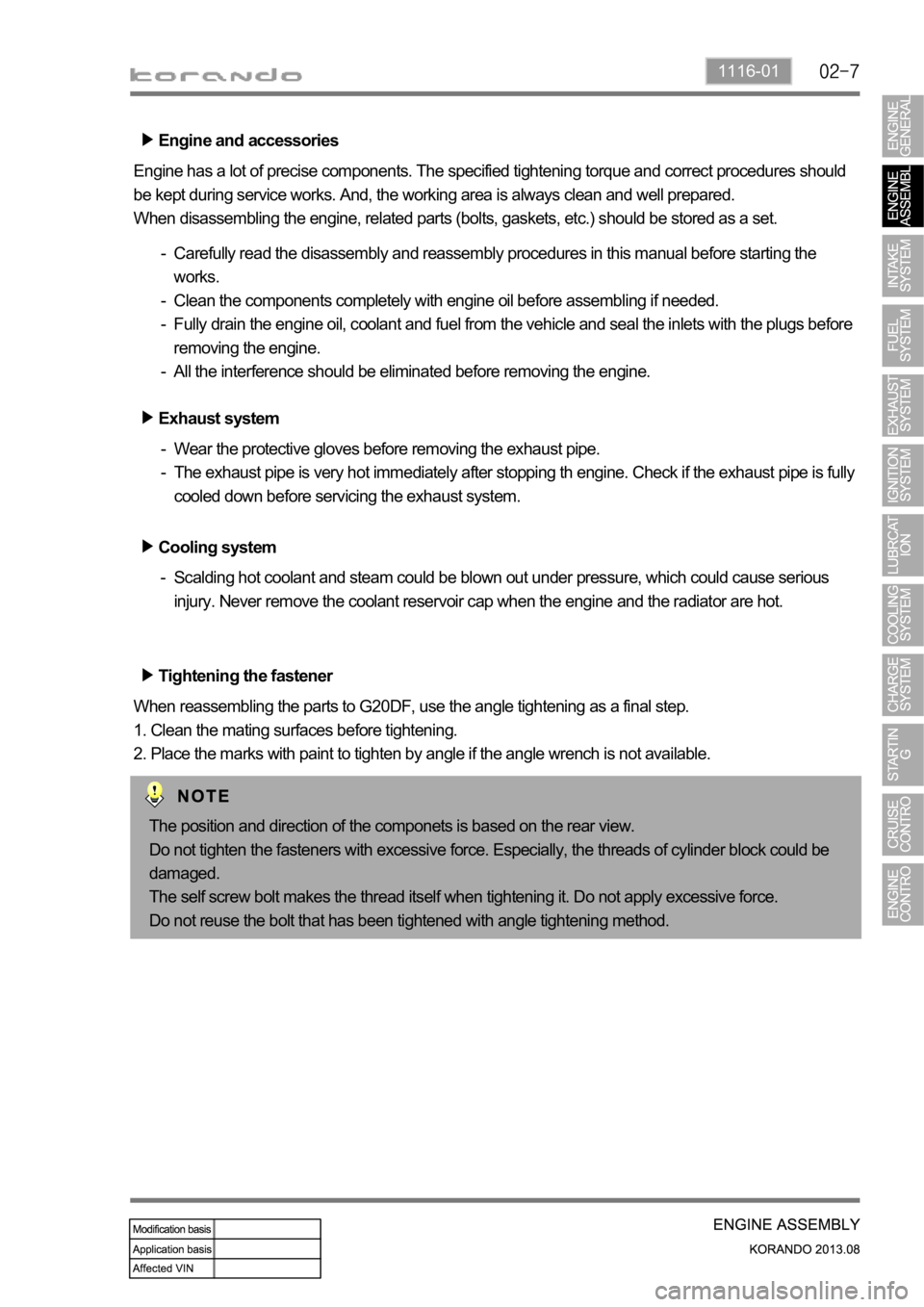
Engine and accessories
Engine has a lot of precise components. The specified tightening torque and correct procedures should
be kept during service works. And, the working area is always clean and well prepared.
When disassembling the engine, related parts (bolts, gaskets, etc.) should be stored as a set.
Carefully read the disassembly and reassembly procedures in this manual before starting the
works.
Clean the components completely with engine oil before assembling if needed.
Fully drain the engine oil, coolant and fuel from the vehicle and seal the inlets with the plugs before
removing the engine.
All the interference should be eliminated before removing the engine. -
-
-
-
Tightening the fastener
When reassembling the parts to G20DF, use the angle tightening as a final step.
1. Clean the mating surfaces before tightening.
2. Place the marks with paint to tighten by angle if the angle wrench is not available. Exhaust system
Wear the protective gloves before removing the exhaust pipe.
The exhaust pipe is very hot immediately after stopping th engine. Check if the exhaust pipe is fully
cooled down before servicing the exhaust system. -
-
Cooling system
Scalding hot coolant and steam could be blown out under pressure, which could cause serious
injury. Never remove the coolant reservoir cap when the engine and the radiator are hot. -
The position and direction of the componets is based on the rear view.
Do not tighten the fasteners with excessive force. Especially, the threads of cylinder block could be
damaged.
The self screw bolt makes the thread itself when tightening it. Do not apply excessive force.
Do not reuse the bolt that has been tightened with angle tightening method.
Page 453 of 1336
5) Cylinder Head Gasket
The cylinder head gasket is installed between cylinder block and cylinder head to seal the combustion
gas from the combustion chamber, engine oil and coolant.Overview
Location
Cylinder head gasket
3 Layer MLS Gasket
Thickness : 0.7 mm (Compressed)
PFP: Max. 85 bar -
-
-
Page 470 of 1336
1128-01
Front view
Rear view
Spring pin (cylinder head mounting)
Expansion plug (exhaust: 6)
Screw plug (water jacket plug) (30Nm)
Screw plug (oil gallery plug)
Spring pin (T.G.C.C) A.
B.
C.
D.
E.
Overview
The cylinder block is made of special cast iron, and contains the major components such as cylinder
head, crankshaft and piston assembly. There are oil and coolant galleries to lubricate and cool the
engine.
Components
Plug screw (water jacket plug) (70Nm)
Expansion plug (intake: 4)
Spring pin (A/C mounting)
Oil gallery (oil filter assembly)
Ctankshaft position sensor mounting
Plug screw (oil gallery plug)
Spring pin (RR seal mounting) A.
B.
C.
D.
E.
F.
G.
Page 471 of 1336
Engine oil
Coolant
Coolant and oil flows
Cylinder head
Cylinder block water
jacket
Coolant pumpCoolant pipe
Thermostat
Supply line to cylinder head
Oil pumpSupply line to PCJ
Main bearing
Oil filter assembly
Page 500 of 1336
1443-01
1. OVERVIEW
The ignition system is to supply high voltage generated from the ignition coil to the spark plug. The
G20DF engine is equipped with the independent type direct ignition system that the ignition coil is
installed in each cylinder.
The basic ignition timing in each cylinder is determined by the signals from camshaft position sensor and
crankshaft position sensor.
This ignition system controls the electronic ignition timing received from the engine ECU. To control the
ignition timing precisely, the ECU use the information below:
Engine load
Coolant temperature
Intake air temperature
Engine rpm
Camshaft position sensor (CPS)
Crankshaft position sensor (CKS) -
-
-
-
-
-
If the signal from the camshaft position sensor is not delivered to the engine ECU, the ignition coil and
fuel system cannot be operated.
Page 502 of 1336
1443-01
Electric throttle valveT-MAP sensorAccelerator pedal position
sensor
Coolant temperature
sensor
Engine ECU
Crankshaft position
sensor
Page 516 of 1336
1) Coolant Level Check
Park the vehicle on level ground and apply the parking brake. Stop the engine and wait until it is
cooled down. The coolant level should be between the MAX and MIN mark on the coolant reservoir.A.
B.
Coolant reservoir
Scalding hot coolant and steam could be blown out under pressure, which could cause serious injury.
Never remove the coolant reservoir cap when the engine and radiator are hot.
Avoid any direct contact of the coolant to the painted body of the vehicle. -
-