Page 528 of 1336
1452-01
2) Battery
Battery assembly
Clamp - Battery
Bolt
Cable assembly - Cable positive
Cable assembly - Battery ground
Bolt - Earth
Cap - Terminal
Connector - Battery 1.
2.
3.
5.
6.
8.
9.
10.Nut
Nut
Cab - Earth
Box assembly - Battery sub
Fuse - MID 80A
Clamp - Battery cable
Grommet - Ring terminal
Grommet - Ring terminal 17.
18.
20.
21.
22.
23.
24.
25.
Page 578 of 1336
(2) Wiring Connection of CAN Communication
Splice pack Wiring Location
S101 Floor wiring (LH)Under fuse & relay box in engine
compartment
S102 Floor wiring (RH) Inside of right fender
S201 Main wiringBehind instrument cluster (cowl cross
member)
S202 Main wiringBehind instrument cluster (cowl cross
member)
S205 Floor wiring (LH)
Page 632 of 1336
3. MAJOR CHANGES
Changes for engine compartment fuse box
8410-02 Engine compartment fuse box
- Changed layout
Name Changes made
A ALT terminal and fuse (150A) Newly adopted
B A/C compressor relay Changed to PCB type
C Headlamp high beam Changed to PCB type
D Rear glass/heated mirror relay Changed to PCB type
E Cooling fan high-speed relay Changed to Micro type
F Blower motor relay Changed to Micro type
G Cooling fan low-speed relay Changed to Micro type
H Cooling fan relay Changed to Micro type
I Fuel heater relay Changed to Micro type
J PTC1 heater relay Changed to Micro type
K Power window relay Changed to Micro type
L Starting relay Changed to Micro type
Page 633 of 1336
8410-00
8410-02 Changed connector position
- Change position of connectors A, B and D
8410-02 Changed connector D
8410-02 Interior fuse box
- Interior fuse box label changed
Page 634 of 1336
ICM box
Interior fuse boxEngine compartment
fuse box
The fuse and relay boxes in this vehicle are mounted on the engine compartment, left side of the
instrument panel and rear of the instrument cluster (3 off in total). The capacities and its names for each
fuse and relay are marked on the each fuse and relay box cover.
The label attached on each fuse box indicates only major fuses and relays. For detailed information, see
the power distribution circuit diagram.
1. OVERVIEW
2. SYSTEM LAYOUT
Page 931 of 1336
7810-00
BCM
The rain sensor detects the amount of rain drops and sends the operating request signal to the BCM,
which drives the wiper directly. At this moment, the BCM also sends the information on whether the
wiper is in operation mode or whether the multifunction wiper switch is in AUTO position to the rain
sensor.
BCM Underhood Fuse Box
Page 997 of 1336

0000-00
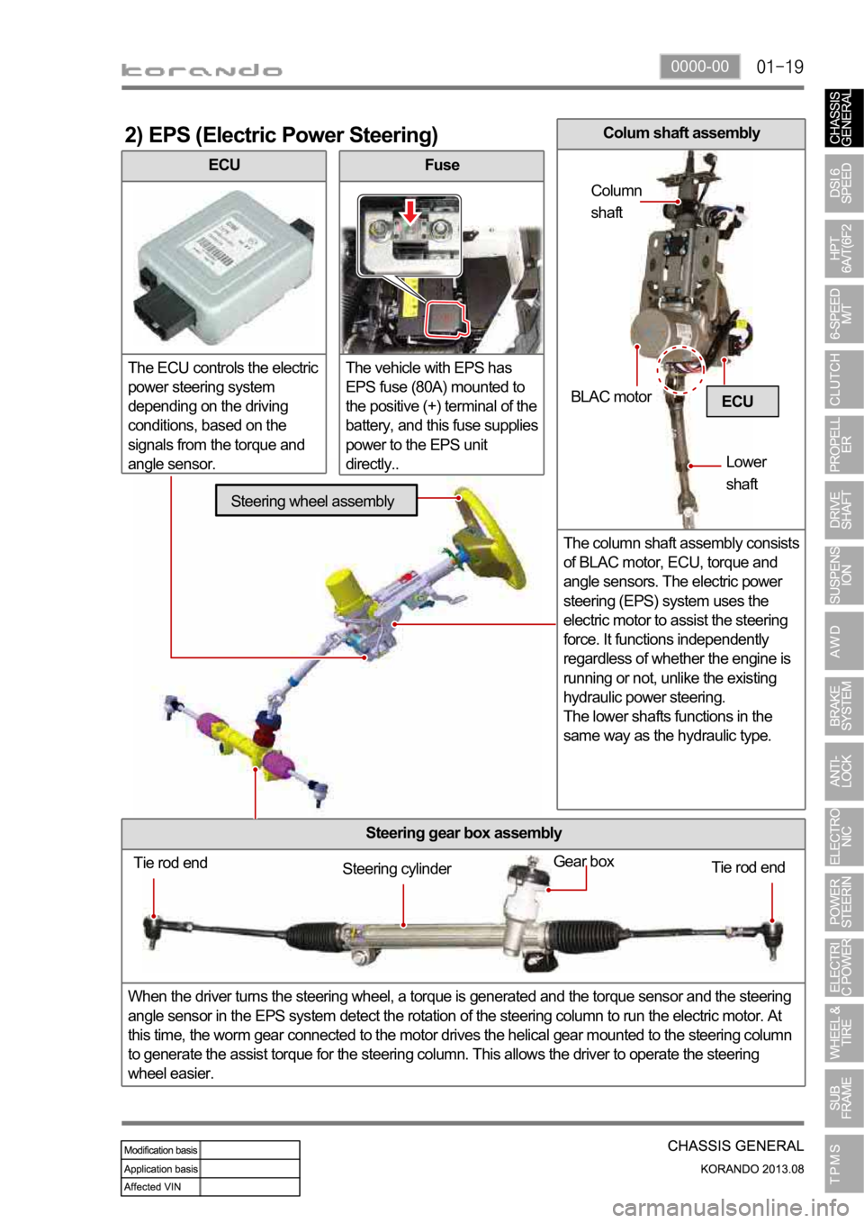
ECU
The ECU controls the electric
power steering system
depending on the driving
conditions, based on the
signals from the torque and
angle sensor.
2) EPS (Electric Power Steering)
Fuse
The vehicle with EPS has
EPS fuse (80A) mounted to
the positive (+) terminal of the
battery, and this fuse supplies
power to the EPS unit
directly..
Steering gear box assembly
When the driver turns the steering wheel, a torque is generated and the torque sensor and the steering
angle sensor in the EPS system detect the rotation of the steering column to run the electric motor. At
this time, the worm gear connected to the motor drives the helical gear mounted to the steering column
to generate the assist torque for the steering column. This allows the driver to operate the steering
wheel easier.
ECU
Tie rod end
Tie rod end Gear boxSteering cylinder
Steering wheel assembly
BLAC motor
Lower
shaft Column
shaft
Colum shaft assembly
The column shaft assembly consists
of BLAC motor, ECU, torque and
angle sensors. The electric power
steering (EPS) system uses the
electric motor to assist the steering
force. It functions independently
regardless of whether the engine is
running or not, unlike the existing
hydraulic power steering.
The lower shafts functions in the
same way as the hydraulic type.