Page 113 of 219

110
Antilock Braking System (ABS)
111
Traction Contr")
Assist systems
Brake assist systems
Introduction
This chapter contains information on the following subjects:
Electronic Stability Control (ESC)
110
Antilock Braking System (ABS)
111
Traction Control System (ASR)
111
Electronic Differential Lock (EDL)
111WARNING■ A lack of fuel can cause irregular engine running or cause the engine to shut
down. The brake assist systems would then fail to function – risk of accident!■
Adjust the speed and driving style to the current visibility, weather, road and
traffic conditions. The increased safety provided by the brake assist systems
must not tempt you to take safety risks – risk of accident!
■
In the event of an ABS fault, visit a specialist garage immediately. Adjust
your style of driving according to the damage to the ABS, as you will not know
the exact extent of the damage or the extent to which this is limiting the
braking efficiency.
CAUTION
■ All four wheels must be fitted with the same tyres approved by the manufactur-
er to ensure the brake assist systems operate correctly.■
Changes to the vehicle (e.g. to the engine, brakes, chassis) can influence the
functionality of the brake assist systems » page 146, Services, modifications and
technical alterations .
■
If a fault occurs in the ABS system, the ESC, TCS and EDL will also fail to work.
An ABS fault is indicated with the warning light » page 24 .
Electronic Stability Control (ESC)
First read and observe the introductory information and safety warn-
ings
on page 110.
The ESC system helps improve control of the vehicle in situations where it is be-
ing operated at its dynamic limits, such as a sudden change to the direction of
travel. Depending on the road surface conditions, the risk of skidding is reduced,
thereby improving the vehicle's driving stability .
The ESC system is automatically activated each time the ignition is switched on.
The direction which the driver wishes to take is determined based on the steering angle and the speed of the vehicle and is constantly compared with the actual
behaviour of the vehicle. In the event of deviations, such as the car beginning to
skid, the ESC system will automatically brake the appropriate wheel.
During an intervention of the system, the warning light
flashes in the instru-
ment cluster.
The following systems are integrated into the electronic stabilisation control
(ESC) :
› Antilock brake system (ABS),
› Traction control (TCS),
› Electronic Differential Lock (EDL)
› Hydraulic Brake Assist (HBA)
› Hill Hold Control (HHC).
The ESC system cannot be deactivated. The
» Fig. 99 on page 111 button can
only be used to deactivate the TCS. The
warning light comes on in the instru-
ment cluster when the TCS is deactivated.
In the event of an ESC fault, the ESC warning light illuminates in the instrumentcluster
» page 23 .
Hydraulic Brake Assist (HBA)
HBA increases the braking effect and helps to shorten the braking distance.
The HBA is activated by very quick operation of the brake pedal. In order to ach-
ieve the shortest possible braking distance, the brake pedal must be applied firm-
ly until the vehicle has come to a standstill.
The HBA function is automatically switched off when the brake pedal is released. The ABS is activated faster and more effectively with the intervention of the HBA.
110Driving
Page 114 of 219

When driving on slopes, HHC allows you to move your foot from the brake pedal
to the accelerator pedal without having to use the handbrake.
The system holds the brake pressure")
Hill Hold Control (HHC)
When driving on slopes, HHC allows you to move your foot from the brake pedal
to the accelerator pedal without having to use the handbrake.
The system holds the brake pressure produced by the activation of the brakepedal for approx. 2 seconds after the brake pedal is released.
The brake pressure drops gradually the more you operate the accelerator pedal. Ifthe vehicle does not start off within 2 seconds, it starts to roll back.
HHC is active on slopes of >5 % when the driver door is closed. HHC is always only
active on slopes when in forward or reverse start off. When driving downhill, it is inactive.
Antilock Braking System (ABS)
First read and observe the introductory information and safety warn-
ings
on page 110.
ABS prevents the wheels locking when braking. Thus helping the driver to main-
tain control of the vehicle.
The intervention of the ABS is noticeable from the pulsating movements of the
brake pedal which is accompanied by noises.
When the ABS system is active, do not brake periodically or reduce the pressure
on the brake pedal.
Traction Control System (ASR)
Fig. 99
TCS buttonFirst read and observe the introductory information and safety warn-
ings on page 110.
If the wheels are slipping, the ASR system adapts the engine speed to the condi-
tions of the road surface. The TCS makes it much easier to start off, accelerate
and climb steep hills even if the conditions of the road surface are unfavourable.
The TCS function is automatically activated each time the ignition is switched on.
During an intervention of the system, the TCS warning light flashes in the in-
strument cluster.
The TCS should normally always be enabled. Only in certain exceptional circum-
stances can it be sensible to switch the system off, for instance:
› when driving with snow chains;
› when driving in deep snow or on a very loose surface;
› when it is necessary to “rock a vehicle free” when it has got stuck.
Ensure the TCS is activated again afterwards.
You can switch TCS off and on again as needed by pressing the
button » Fig. 99 .
The
warning light comes on in the instrument cluster when the TCS is deactiva-
ted.
The TCS warning light
» page 26 lights up in the instrument cluster when there
is a fault on the TCS.
Electronic Differential Lock (EDL)
First read and observe the introductory information and safety warn-
ings
on page 110.
If one of the wheels starts to spin, the EDL system brakes the spinning wheel and
transfers the driving force to the other wheels. This ensures the stability of the
vehicle and a quick journey.
EDL switches off automatically to avoid excessive heat generation on the brake of the wheel being braked. The vehicle can continue to be driven and has the
same characteristics as a vehicle not fitted with EDL. The EDL switches on again
automatically as soon as the brake has cooled down.
111Assist systems
Page 115 of 219

Parking aid
Introduction
This chapter contains information on the following subjects:
Function
112
Activation/deactivation
113WARNING■ The parking aid is not a substitute for the driver paying proper attention and
it is always the driver's responsibility to take care when reversing the vehicle
or carrying out similar manoeuvres. Pay particular attention to small children
and animals as they are not recognised by the parking aid sensors.■
Before reversing, you should make sure that there are no small obstacles,
such as rocks, thin posts, trailer drawbars etc. behind your vehicle. Such ob-
stacles may not be recognised by the parking aid sensors.
■
Under certain circumstances, surfaces of certain objects and types of cloth-
ing cannot reflect the system signals. Thus, these objects or people who wear
such clothing are not recognised by the System sensors.
■
External sound sources can have a detrimental effect on the system. Under
adverse conditions, this may cause objects or people to not be recognised by the system.
CAUTION
■ If a warning signal sounds for about 3 seconds after activating the system and
there is no obstacle close to your car, this indicates a system fault. Have the fault
rectified by a specialist garage.■
The sensors must be kept clean (free of ice, etc.) to enable the parking aid to
operate properly.
■
Under adverse weather conditions (heavy rain, water vapour, very low or high
temperatures etc.) system function may be limited.
■
Additionally installed modules such as bicycle carriers can impair the function of
the parking aid.
FunctionFig. 100
Parking aid: Range of sensors
First read and observe the introductory information and safety warn- ings on page 112.
The parking aid (referred to below solely as system) only works when the ignition
is switched on.
The system supports the driver via audible signals, via the display on the radio or
via the factory-installed navigation system when parking and manoeuvring » Ra-
dio user guide, Navigation system user guide.
The system uses ultrasound waves to calculate the distance between the bumper
and an obstacle. The ultrasonic sensors are integrated in the rear bumper.
Range of sensors
The clearance warning begins at a distance of about 160 cm from the obstacle
(area
A
» Fig. 100 ). The interval between the warning signals becomes shorter as
the clearance is reduced.
A continuous tone sounds from a distance of approx. 30 cm (area
B
) - danger
area. You should not reverse any further after this signal sounds!
On vehicles with a factory-fitted towing device, the border of the danger area starts (continuous tone) 5 cm further away from the vehicle. The length of the ve-
hicle can be increased with an installed detachable towing device.
112Driving
Page 116 of 219

Activation/deactivationFirst read and observe the introductory information and safety warn-
ings
on page 112.
The system is activated automatically by engaging reverse gear. This is confirmed
by a brief audible signal.
The system is deactivated by disengaging reverse gear.
Note
The system cannot be activated on vehicles with a factory-fitted towing device
when towing a trailer.
Cruise Control System
Introduction
This chapter contains information on the following subjects:
Storing a speed
114
Changing a stored speed
114
Switching off temporarily
114
Switching off completely
114
The Cruise Control System (CCS) maintains a set speed, more than 25 km/h, with-
out you having to actuate the accelerator pedal.
This is only possible within the range which is permitted by the power output and
braking power of the engine.
The
warning light in the instrument cluster lights up when the cruise control
system is switched on.
WARNING■ For safety reasons, the cruise control system must not be used in dense
traffic or on unfavourable road surfaces (such as icy roads, slippery roads,
loose gravel) – there is a risk of an accident.■
The saved speed may only be resumed if it is not too high for the current
traffic conditions.
■
Always deactivate the cruise control system after use to prevent the system
being switched on unintentionally.
CAUTION
■ The cruise control system is not able to maintain a constant speed when driving
in areas with steeper gradients. The weight of the vehicle increases the speed at which it travels. Therefore, shift to a lower gear in good time or slow the vehicle
down by applying the foot brake.■
It is not possible to switch on the cruise control system on vehicles fitted with a
manual gearbox if the first gear or reverse gear is engaged.
■
It is not possible on vehicles fitted with an automatic gearbox to switch on the
cruise control system if the selector lever is in the position P, N or R.
■
The Cruise Control System may automatically switch off when some brake as-
sist systems (e.g. ESC) intervene, when the speed exceeds maximum permissible
engine speed, or a similar event takes place.
113Assist systems
Page 117 of 219

Storing a speedFig. 101
Operating lever: Operating the
cruise control system
First read and observe the introductory information and safety warn-
ings on page 113.
Storing a speed
›
Press switch
A
» Fig. 101 to the ON position.
›
After the desired speed has been reached, press the rocker button
B
into the
SET position.
After you have released the rocker button
B
out of the position SET, the speed
you have just stored is maintained at a constant speed without having to depress
the accelerator.
Changing a stored speed
First read and observe the introductory information and safety warn-
ings
on page 113.
Increasing the speed with the accelerator
›
Depress the accelerator to increase the speed.
›
Release the accelerator to reduce the speed back down to the preset speed.
However, if the saved speed is exceeded by more than 10 km/h for a period of
more than 5 minutes by depressing the accelerator, the stored speed is deleted from the memory. The speed must then be saved again.
Increasing the speed with the rocker button
B›
Press rocker button
B
» Fig. 101 on page 114 to the RES position.
›
The speed will increase continuously, if the rocker button is pressed and held in
the RES position. Release the rocker button once the desired speed is reached.
The set speed is then stored in the memory.
Decreasing the speed›The stored speed can be reduced by pressing rocker button B » Fig. 101 on
page 114 to the SET position.›
The speed will decrease continuously, if the rocker button is pressed and held in
the SET position. Release the rocker button once the desired speed is reached.
The set speed is then stored in the memory.
›
If the rocker button is released at a speed below around 25 km/h, the speed is not stored and the memory is erased. The speed must then be stored again bypressing rocker button
B
to the SET position after increasing the speed of the
vehicle to more than around 25 km/h.
The speed can also be reduced by depressing the brake pedal, which temporarily
deactivates the system.
Switching off temporarily
First read and observe the introductory information and safety warn-
ings
on page 113.
The cruise control system can be temporarily switched off by pushing switch
A
» Fig. 101 on page 114 to the spring-loaded CANCEL position or by depressing
the brake or clutch pedal.
The set speed remains stored in the memory.
Briefly push rocker button
B
to the RES position to resume the set speed after
the clutch or brake pedal is released.
Switching off completely
First read and observe the introductory information and safety warn-
ings
on page 113.
›
Press switch
A
» Fig. 101 on page 114 to the right to the OFF position.
114Driving
Page 118 of 219

START-STOP
Introduction
This chapter contains information on the following subjects:
Starting/shutting down the engine
115
Operating conditions for the system
115
Manually activating/deactivating the system
116
Information messages
116
The START-STOP system helps you to save fuel while at the same time reducing
harmful exhaust emissions and CO 2 emissions.
The function is automatically activated each time the ignition is switched on.
In the start-stop mode, the engine automatically switches to the vehicle's idle phase, e.g. when stopped at traffic lights. The engine restarts automatically
where necessary.
The system can work only if the following basic conditions are met. The driver's door is closed.
The driver has fastened the seat belt. The bonnet is closed.The driving speed exceeded 4 km/h after the last stop.
No trailer is coupled.
WARNING■ The brake servo unit and power steering only operate if the engine is run-
ning.■
Never let the vehicle roll with the engine switched off.
CAUTION
Always deactivate the START-STOP system before driving through wa-
ter » page 108 .Note■
If the driver's seat belt is removed for more than 30 seconds or the driver's door
is opened during stop mode, the engine will have to be started manually.■
After manually starting the engine, automatic engine shut down is not possible
until the vehicle has travelled the required minimum distance for START-STOP mode.
■
Changes to the outdoor temperature can have an effect on the internal temper-
ature of the vehicle battery even after several hours. If the vehicle remains out-
doors for a long time in minus temperatures or in direct sunlight, it can take sev-
eral hours until the internal temperature of the vehicle battery reaches a suitable
temperature for proper operation of the START STOP system.
■
If Climatronic is running in automatic mode, the engine may not switch off auto-
matically under certain conditions.
Starting/shutting down the engine
First read and observe the introductory information and safety warn-ings
on page 115.
›
Stop the vehicle (where necessary, apply the handbrake).
›
Shift the gear lever to Neutral.
›
Release the clutch pedal.
Automatic engine shut down (STOP phase) runs. The
warning symbol appears
in the instrument cluster display.
›
Depress the clutch pedal.
The new start procedure runs (START phase). The
warning symbol goes out.
Operating conditions for the system
First read and observe the introductory information and safety warn-
ings
on page 115.
The START-STOP system is very complex. Some of the procedures are hard to check without servicing.
No engine shut down runs
Before each STOP phase, the system checks whether certain conditions have
been met. No engine shut down runs in the following situations.
115Assist systems
Page 119 of 219

›The engine has not yet reached the minimum temperature for the START STOP
mode.
› The temperature inside the vehicle has not reached the desired temperature
set in the air-conditioning system/heating.
› The external temperature is very low/high.
› Intensive windscreen deicing (Climatronic) or windscreen deicing/ventilation is
switched on at the maximum air temperature setting (manual air conditioning
system).
› The parking aid is activated.
› The charge state of the vehicle battery is too low.
› The stationary vehicle is on a steep hill or a steep slope.
› The idling speed is too high.
› The steering angle is too great (manoeuvring).
The
warning symbol is being shown in the instrument cluster display.
The automatic start procedure runs again During the STOP phase, the engine fires up without any active driver intervention,
e.g. in the following situations.
› The vehicle has begun to roll, e.g. on a slope.
› The difference between the temperature setting of the air-conditioning sys-
tem/heating and the temperature of the interior is too great.
› Intensive windscreen deicing (Climatronic) or windscreen deicing/ventilation is
switched on at the maximum air temperature setting (manual air conditioning
system).
› The brake pedal was pressed several times (the pressure in the braking system
is too low).
› The charge state of the vehicle battery is too low.
› The current consumption is too high.
Manually activating/deactivating the system
Fig. 102
Button for the START-STOP sys-
tem
First read and observe the introductory information and safety warn-
ings on page 115.
Activation/deactivation
›
Press the button » Fig. 102 .
When start-stop mode is deactivated, the warning light in the button lights up.
Note
If the system is deactivated during the STOP phase, the automatic start proce-
dure runs.
Information messages
First read and observe the introductory information and safety warn-
ings
on page 115.
The messages and information are indicated in the instrument cluster display.
Start the engine manually.START MANUALLY
The driver sees this message when the conditions for the automatic start proce- dure are not met during the STOP phase. The engine must be started manually.
Fault: start-stop system
ERROR START-STOP
Fault in the START-STOP system. Seek help from a specialist garage.
116Driving
Page 120 of 219

Towing a trailer
Towing device
Introduction
This chapter contains information on the following subjects:
Description
117
Adjusting the ready position
118
Fitting the ball head
118
Check proper fitting
119
Removing the ball head
119
Use and care
120
If your vehicle has already been factory-fitted with towing equipment or is fitted
with towing equipment from ŠKODA Original Accessories, then it meets all of the technical requirements and national legal provisions for towing a trailer.
Your vehicle is fitted with a 13-pin power socket for the electrical connection be-tween the vehicle and trailer. If the trailer that is to be towed has a 7-pin connec-
tor , you can use a suitable adapter from ŠKODA Original Accessories.
The maximum trailer drawbar load is 50 kg/h.
WARNING■
Check that the ball head is seated correctly and is secured in the mounting
recess before starting any journey.■
Do not use the ball head if it is not correctly inserted in the mounting recess.
■
Do not use the towing equipment if it is damaged or incomplete.
■
Do not modify or adapt the towing equipment in any way.
■
Never release the ball head while the trailer is still coupled.
CAUTION
Take care with the ball head to avoid damaging the paintwork on the bumper.
DescriptionFig. 103
Remove cover cap: on the rear bumper/for the mounting recess
Fig. 104
Ball head
First read and observe the introductory information and safety warn-
ings on page 117.
The ball head can be removed and is kept in the spare wheel well or in a compart- ment for the spare wheel in the luggage compartment » page 180, Vehicle tool
kit .
Image description » Fig. 103 and » Fig. 104
Clamps for removing the wheel trims
Cover in the rear bumper
13-pin power socket
Cover for the mounting recess
Dust cap
Ball head
Operating lever
1234567117Towing a trailer
 1
1 2
2 3
3 4
4 5
5 6
6 7
7 8
8 9
9 10
10 11
11 12
12 13
13 14
14 15
15 16
16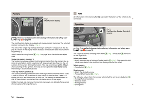 17
17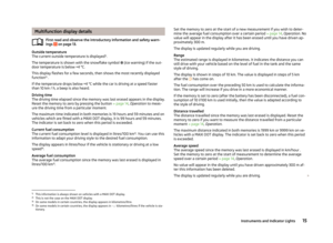 18
18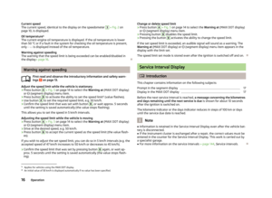 19
19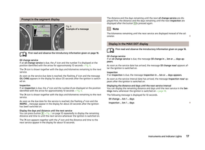 20
20 21
21 22
22 23
23 24
24 25
25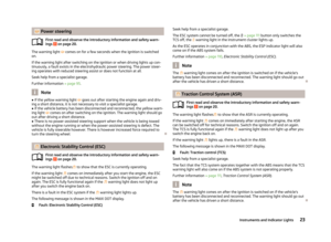 26
26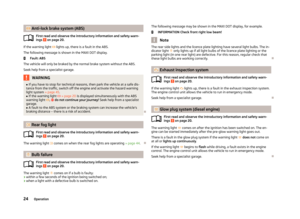 27
27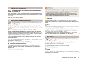 28
28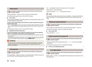 29
29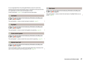 30
30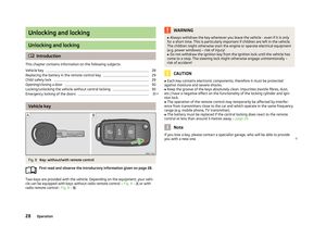 31
31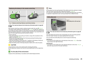 32
32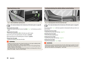 33
33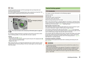 34
34 35
35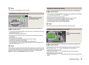 36
36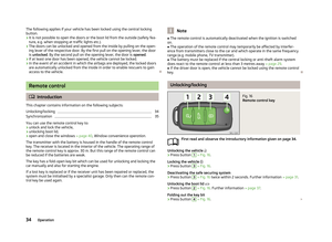 37
37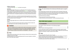 38
38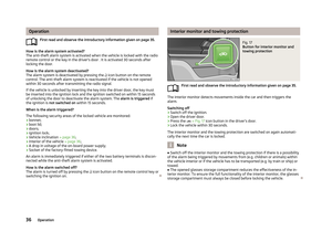 39
39 40
40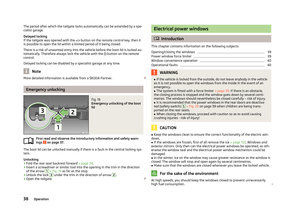 41
41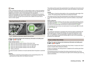 42
42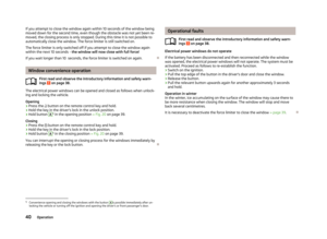 43
43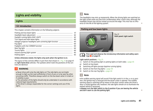 44
44 45
45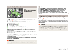 46
46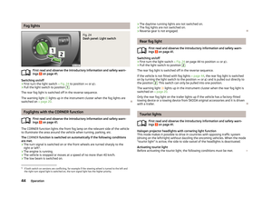 47
47 48
48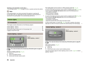 49
49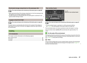 50
50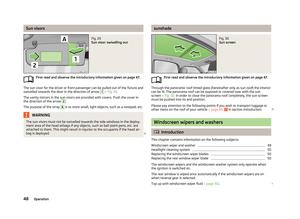 51
51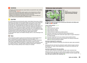 52
52 53
53 54
54 55
55 56
56 57
57 58
58 59
59 60
60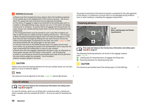 61
61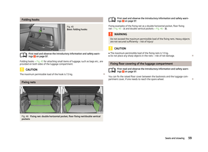 62
62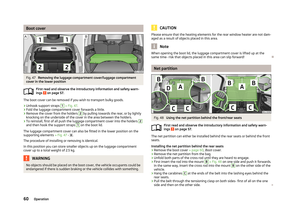 63
63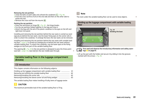 64
64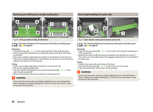 65
65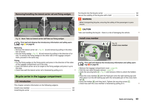 66
66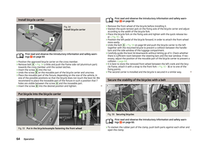 67
67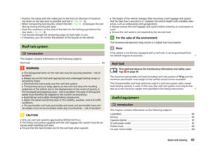 68
68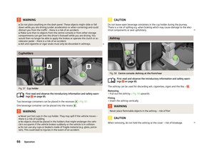 69
69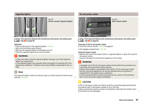 70
70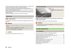 71
71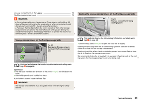 72
72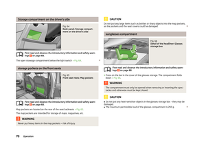 73
73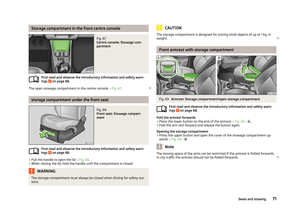 74
74 75
75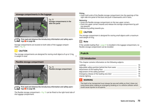 76
76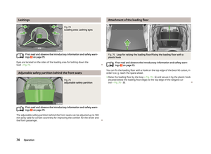 77
77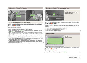 78
78 79
79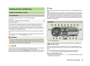 80
80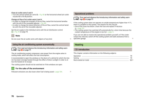 81
81 82
82 83
83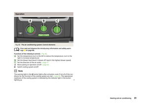 84
84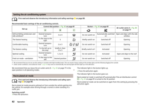 85
85 86
86 87
87 88
88 89
89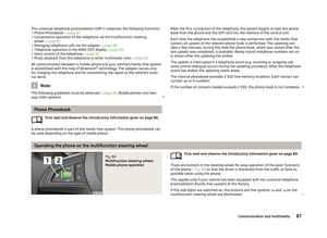 90
90 91
91 92
92 93
93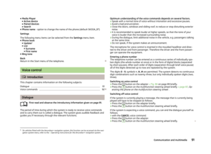 94
94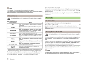 95
95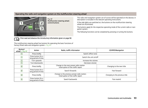 96
96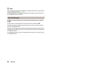 97
97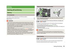 98
98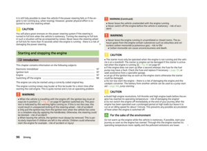 99
99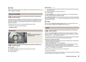 100
100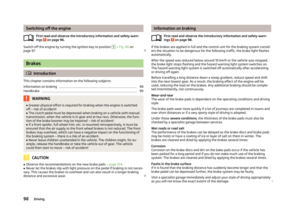 101
101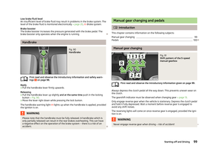 102
102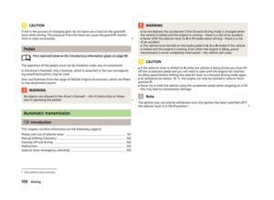 103
103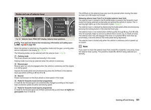 104
104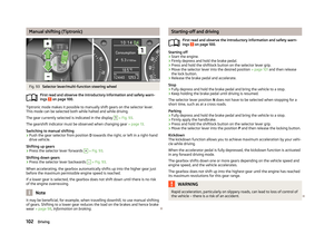 105
105 106
106 107
107 108
108 109
109 110
110 111
111 112
112 113
113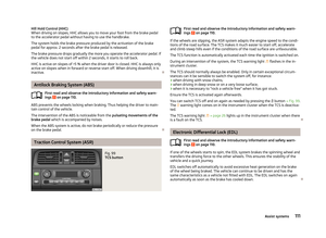 114
114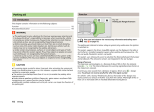 115
115 116
116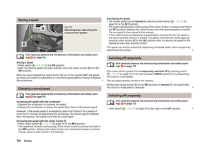 117
117 118
118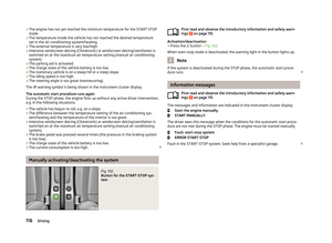 119
119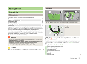 120
120 121
121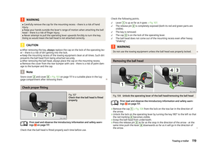 122
122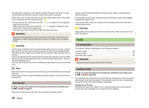 123
123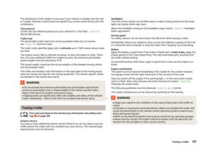 124
124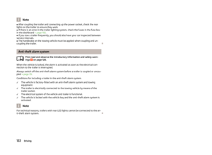 125
125 126
126 127
127 128
128 129
129 130
130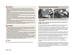 131
131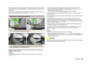 132
132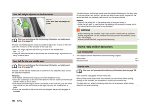 133
133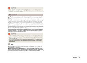 134
134 135
135 136
136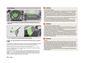 137
137 138
138 139
139 140
140 141
141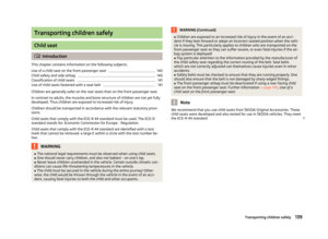 142
142 143
143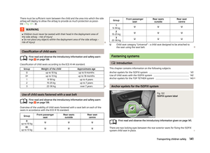 144
144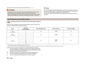 145
145 146
146 147
147 148
148 149
149 150
150 151
151 152
152 153
153 154
154 155
155 156
156 157
157 158
158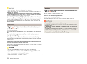 159
159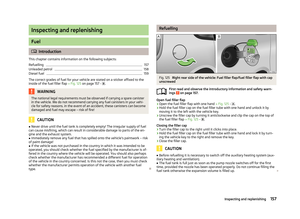 160
160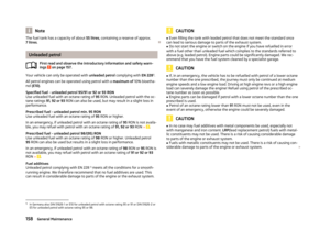 161
161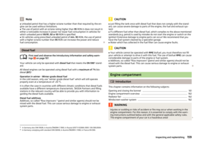 162
162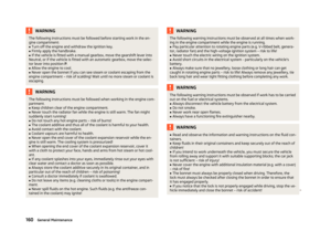 163
163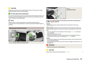 164
164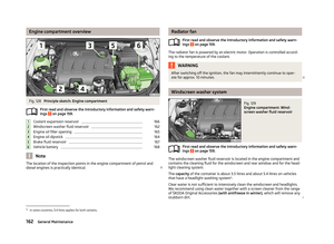 165
165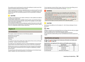 166
166 167
167 168
168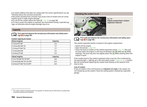 169
169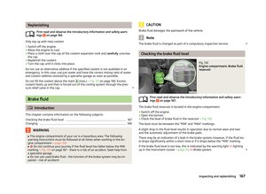 170
170 171
171 172
172 173
173 174
174 175
175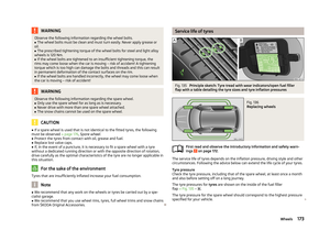 176
176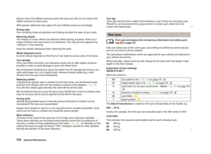 177
177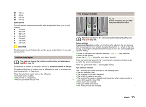 178
178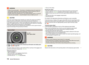 179
179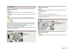 180
180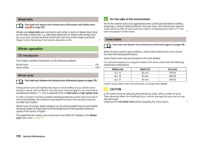 181
181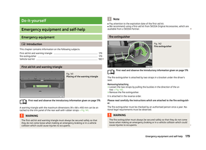 182
182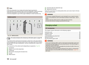 183
183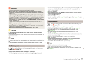 184
184 185
185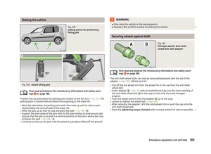 186
186 187
187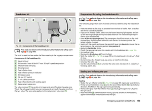 188
188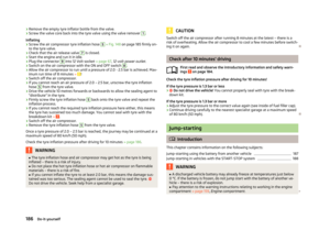 189
189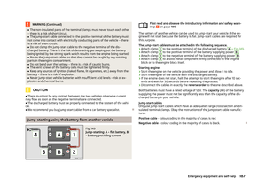 190
190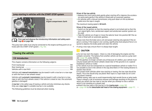 191
191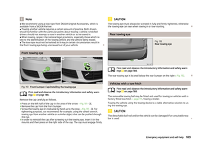 192
192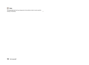 193
193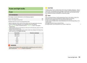 194
194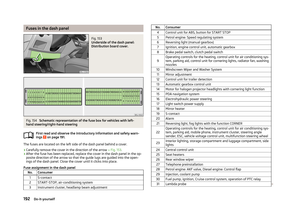 195
195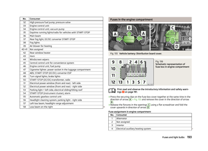 196
196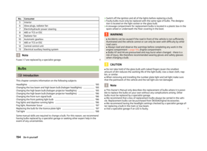 197
197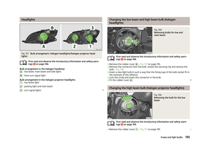 198
198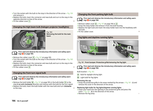 199
199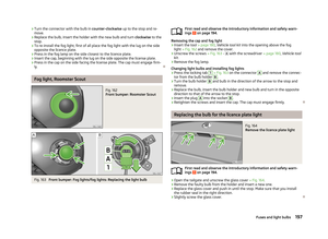 200
200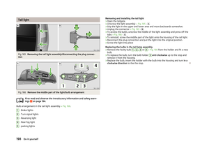 201
201 202
202 203
203 204
204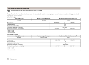 205
205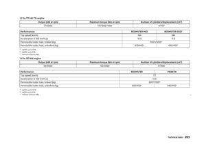 206
206 207
207 208
208 209
209 210
210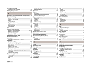 211
211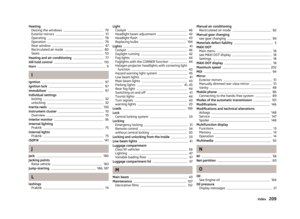 212
212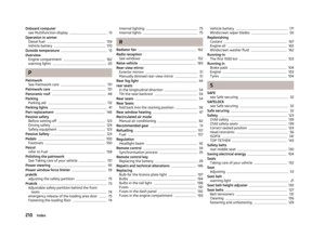 213
213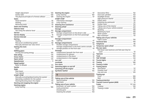 214
214 215
215 216
216 217
217 218
218