2013 NISSAN LEAF display
[x] Cancel search: displayPage 214 of 275
8-8Voice recognition
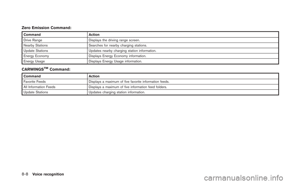
Zero Emission Command:
CommandAction
Drive Range Displays the driving range screen.
Nearby Stations Searches for nearby charging stations.
Update Stations Updates nearby charging station information.
Energy Economy Displays Energy Economy information.
Energy Usage Displays Energy Usage information.
CARWINGSTMCommand:
Command Action
Favorite Feeds Displays a maximum of five favorite information feeds.
All Information Feeds Displays a maximum of five information feed folders.
Update Stations Updates charging station information.
Page 215 of 275
![NISSAN LEAF 2013 1.G Navigation Manual VOICE RECOGNITION SETTINGS
Detailed settings for use of the voice recognition
function can be performed.
1. Push theMENUbutton and touch [Set-
tings].
2. Touch [Others].
3. Touch [Voice Recognition].
NISSAN LEAF 2013 1.G Navigation Manual VOICE RECOGNITION SETTINGS
Detailed settings for use of the voice recognition
function can be performed.
1. Push theMENUbutton and touch [Set-
tings].
2. Touch [Others].
3. Touch [Voice Recognition].](/manual-img/5/324/w960_324-214.png)
VOICE RECOGNITION SETTINGS
Detailed settings for use of the voice recognition
function can be performed.
1. Push theMENUbutton and touch [Set-
tings].
2. Touch [Others].
3. Touch [Voice Recognition].
4. Touch the item you would like to set.
Available settings
. [Command List]:
Displays the voice command list.
“Displaying command list” (page 8-6)
. [Direct Command Mode]:
Switch the voice command mode from the
Standard Mode to the Direct Command
Mode. The Standard Mode is the factory
default setting.
When [Direct Command Mode] is touched, a confirmation message displays. If [Yes] is
touched, the indicator illuminates and the
Direct Command Mode switches to on.
When the Direct Command Mode is not
selected, the system recognizes only the
commands listed on the screen. When the
Direct Command Mode is selected, the
system recognizes the commands that
should be performed in the following steps,
in addition to the commands listed on the
current screen.
. [Minimise Voice Feedback]:
It is possible to select two modes, long or
short, for the announcement made by the
system.
When [Minimise Voice Feedback] is
touched, the indicator illuminates and the
system announcement mode switches to the
short mode.
. [Confirm Voice Commands]:
After speaking a command, the system
requests the user to confirm that the
recognized command by the system is
correct. The confirmation function is set to
off as the default setting.
When the system recognizes a command, a
confirmation message is displayed on the
screen. If the message correctly matches
your command, say "Yes" and continue the voice command operation. If the message is
incorrect, say "No" and return to the
previous screen.
Voice recognition8-9
Page 217 of 275
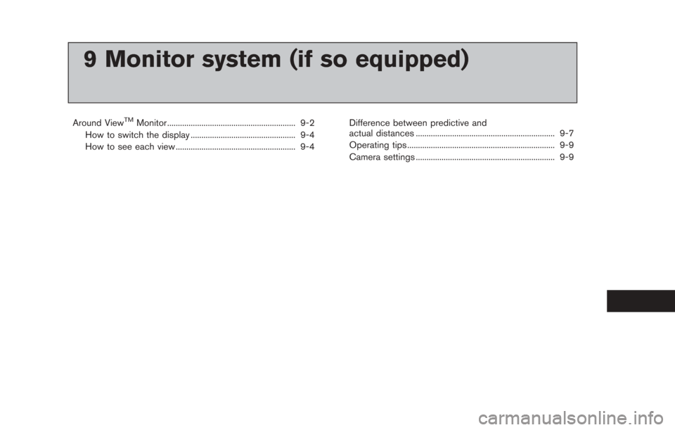
9 Monitor system (if so equipped)
Around ViewTMMonitor ............................................................ 9-2
How to switch the display ................................................. 9-4
How to see each view ........................................................ 9-4 Difference between predictive and
actual distances ................................................................. 9-7
Operating tips ..................................................................... 9-9
Camera settings ................................................................. 9-9
Page 218 of 275
9-2Monitor system (if so equipped)
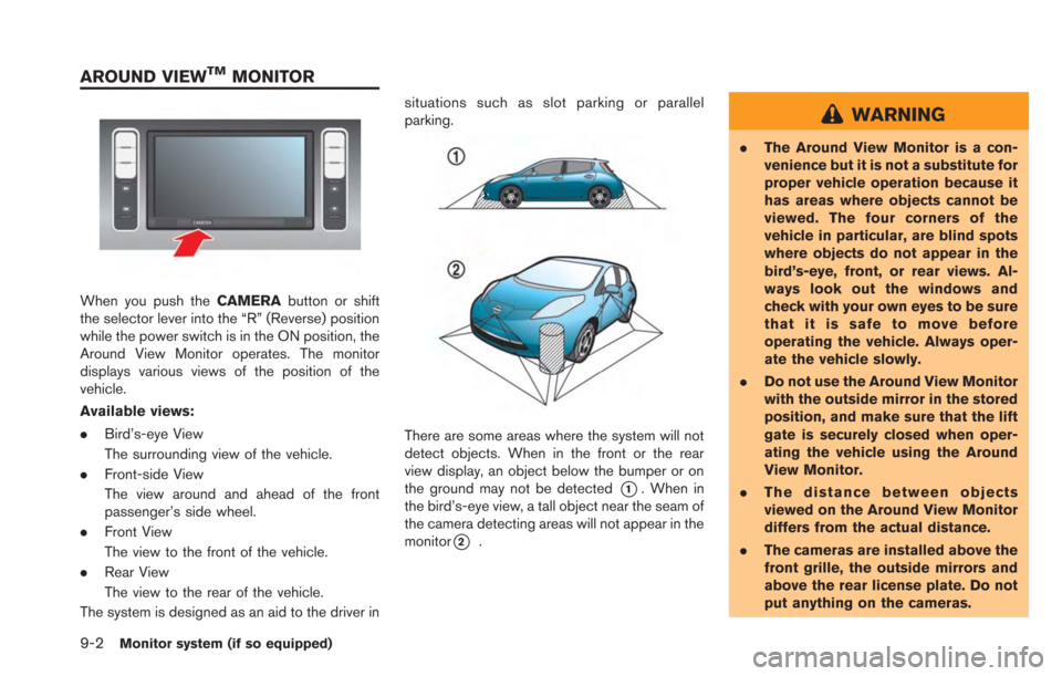
When you push theCAMERAbutton or shift
the selector lever into the “R” (Reverse) position
while the power switch is in the ON position, the
Around View Monitor operates. The monitor
displays various views of the position of the
vehicle.
Available views:
. Bird’s-eye View
The surrounding view of the vehicle.
. Front-side View
The view around and ahead of the front
passenger’s side wheel.
. Front View
The view to the front of the vehicle.
. Rear View
The view to the rear of the vehicle.
The system is designed as an aid to the driver in situations such as slot parking or parallel
parking.
There are some areas where the system will not
detect objects. When in the front or the rear
view display, an object below the bumper or on
the ground may not be detected
*1. When in
the bird’s-eye view, a tall object near the seam of
the camera detecting areas will not appear in the
monitor
*2.
WARNING
. The Around View Monitor is a con-
venience but it is not a substitute for
proper vehicle operation because it
has areas where objects cannot be
viewed. The four corners of the
vehicle in particular, are blind spots
where objects do not appear in the
bird’s-eye, front, or rear views. Al-
ways look out the windows and
check with your own eyes to be sure
that it is safe to move before
operating the vehicle. Always oper-
ate the vehicle slowly.
. Do not use the Around View Monitor
with the outside mirror in the stored
position, and make sure that the lift
gate is securely closed when oper-
ating the vehicle using the Around
View Monitor.
. The distance between objects
viewed on the Around View Monitor
differs from the actual distance.
. The cameras are installed above the
front grille, the outside mirrors and
above the rear license plate. Do not
put anything on the cameras.
AROUND VIEWTMMONITOR
Page 220 of 275
9-4Monitor system (if so equipped)
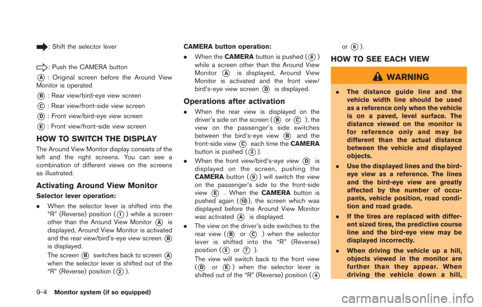
: Shift the selector lever
: Push the CAMERA button
*A: Original screen before the Around View
Monitor is operated
*B: Rear view/bird-eye view screen
*C: Rear view/front-side view screen
*D: Front view/bird-eye view screen
*E: Front view/front-side view screen
HOW TO SWITCH THE DISPLAY
The Around View Monitor display consists of the
left and the right screens. You can see a
combination of different views on the screens
as illustrated.
Activating Around View Monitor
Selector lever operation:
. When the selector lever is shifted into the
“R” (Reverse) position (
*1) while a screen
other than the Around View Monitor
*Ais
displayed, Around View Monitor is activated
and the rear view/bird’s-eye view screen
*B
is displayed.
The screen
*Bswitches back to screen*A
when the selector lever is shifted out of the
“R” (Reverse) position (
*2). CAMERA button operation:
.
When the CAMERA button is pushed (
*8)
while a screen other than the Around View
Monitor
*Ais displayed, Around View
Monitor is activated and the front view/
bird’s-eye view screen
*Dis displayed.
Operations after activation
. When the rear view is displayed on the
driver’s side on the screen (
*Bor*C) , the
view on the passenger’s side switches
between the bird’s-eye view
*Band the
front-side view
*Ceach time the CAMERA
button is pushed (
*3).
. When the front view/bird’s-eye view
*Dis
displayed on the screen, pushing the
CAMERA button (
*9) will switch the view
on the passenger’s side to the front-side
view
*E. When the CAMERAbutton is
pushed again (
*10) , the screen which was
displayed before the Around View Monitor
was activated
*Ais displayed.
. The view on the driver’s side switches to the
rear view (
*Bor*C) when the selector
lever is shifted into the “R” (Reverse)
position (
*5or*7).
The view will switch back to the front view
(
*Dor*E) when the selector lever is
shifted out of the “R” (Reverse) position (
*4
or*6).
HOW TO SEE EACH VIEW
WARNING
. The distance guide line and the
vehicle width line should be used
as a reference only when the vehicle
is on a paved, level surface. The
distance viewed on the monitor is
for reference only and may be
different than the actual distance
between the vehicle and displayed
objects.
. Use the displayed lines and the bird-
eye view as a reference. The lines
and the bird-eye view are greatly
affected by the number of occu-
pants, vehicle position, road condi-
tion and road grade.
. If the tires are replaced with differ-
ent sized tires, the predictive course
line and the bird-eye view may be
displayed incorrectly.
. When driving the vehicle up a hill,
objects viewed in the monitor are
further than they appear. When
driving the vehicle down a hill,
Page 221 of 275
objects viewed in the monitor are
closer than they appear. Use the
mirrors or actually look to properly
judge distances to other objects.
The vehicle width and predictive course lines are
wider than the actual width and course.
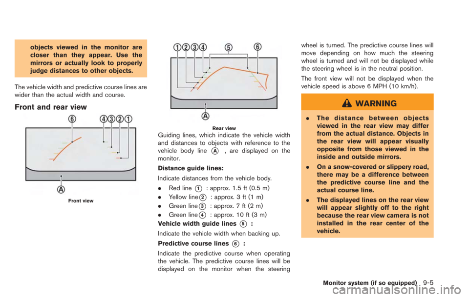
Front and rear view
Front view
Rear viewGuiding lines, which indicate the vehicle width
and distances to objects with reference to the
vehicle body line
*A, are displayed on the
monitor.
Distance guide lines:
Indicate distances from the vehicle body.
. Red line
*1: approx. 1.5 ft (0.5 m)
. Yellow line
*2: approx. 3 ft (1 m)
. Green line
*3: approx. 7 ft (2 m)
. Green line
*4: approx. 10 ft (3 m)
Vehicle width guide lines
*5:
Indicate the vehicle width when backing up.
Predictive course lines
*6:
Indicate the predictive course when operating
the vehicle. The predictive course lines will be
displayed on the monitor when the steering wheel is turned. The predictive course lines will
move depending on how much the steering
wheel is turned and will not be displayed while
the steering wheel is in the neutral position.
The front view will not be displayed when the
vehicle speed is above 6 MPH (10 km/h).
WARNING
.
The distance between objects
viewed in the rear view may differ
from the actual distance. Objects in
the rear view will appear visually
opposite from those viewed in the
inside and outside mirrors.
. On a snow-covered or slippery road,
there may be a difference between
the predictive course line and the
actual course line.
. The displayed lines on the rear view
will appear slightly off to the right
because the rear view camera is not
installed in the rear center of the
vehicle.
Monitor system (if so equipped)9-5
Page 222 of 275
9-6Monitor system (if so equipped)
CAUTION
When the monitor displays the front
view and the steering wheel turns about
90 degrees or less from the neutral
position, both the right and left pre-
dictive course lines
*6are displayed.
When the steering wheel turns about 90
degrees or more, a predictive course
line is displayed only on the opposite
side of the turn.
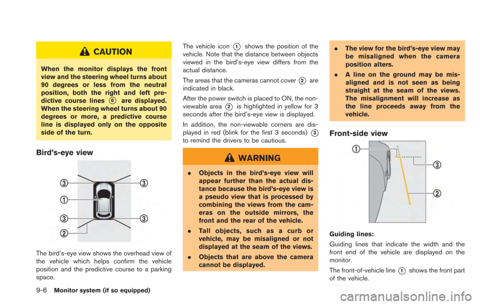
Bird’s-eye view
The bird’s-eye view shows the overhead view of
the vehicle which helps confirm the vehicle
position and the predictive course to a parking
space. The vehicle icon
*1shows the position of the
vehicle. Note that the distance between objects
viewed in the bird’s-eye view differs from the
actual distance.
The areas that the cameras cannot cover
*2are
indicated in black.
After the power switch is placed to ON, the non-
viewable area
*2is highlighted in yellow for 3
seconds after the bird’s-eye view is displayed.
In addition, the non-viewable corners are dis-
played in red (blink for the first 3 seconds)
*3
to remind the drivers to be cautious.
WARNING
. Objects in the bird’s-eye view will
appear further than the actual dis-
tance because the bird’s-eye view is
a pseudo view that is processed by
combining the views from the cam-
eras on the outside mirrors, the
front and the rear of the vehicle.
. Tall objects, such as a curb or
vehicle, may be misaligned or not
displayed at the seam of the views.
. Objects that are above the camera
cannot be displayed. .
The view for the bird’s-eye view may
be misaligned when the camera
position alters.
. A line on the ground may be mis-
aligned and is not seen as being
straight at the seam of the views.
The misalignment will increase as
the line proceeds away from the
vehicle.
Front-side view
Guiding lines:
Guiding lines that indicate the width and the
front end of the vehicle are displayed on the
monitor.
The front-of-vehicle line
*1shows the front part
of the vehicle.
Page 223 of 275
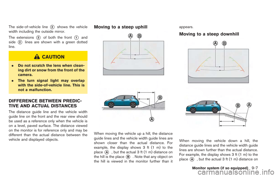
The side-of-vehicle line*2shows the vehicle
width including the outside mirror.
The extensions
*3of both the front*1and
side
*2lines are shown with a green dotted
line.
CAUTION
. Do not scratch the lens when clean-
ing dirt or snow from the front of the
camera.
. The turn signal light may overlap
with the side-of-vehicle line. This is
not a malfunction.
DIFFERENCE BETWEEN PREDIC-
TIVE AND ACTUAL DISTANCES
The distance guide line and the vehicle width
guide line on the front and the rear view should
be used as a reference only when the vehicle is
on a level, paved surface. The distance viewed
on the monitor is for reference only and may be
different than the actual distance between the
vehicle and displayed objects.
Moving to a steep uphill
When moving the vehicle up a hill, the distance
guide lines and the vehicle width guide lines are
shown closer than the actual distance. For
example, the display shows 3 ft (1 m) to the
place
*A, but the actual 3 ft (1 m) distance on
the hill is the place
*B. Note that any object on
the hill is viewed in the monitor further than it appears.
Moving to a steep downhill
When moving the vehicle down a hill, the
distance guide lines and the vehicle width guide
lines are shown further than the actual distance.
For example, the display shows 3 ft (1 m) to the
place
*A, but the actual 3 ft (1 m) distance on
Monitor system (if so equipped)9-7