Page 225 of 275

MOBILITYReplacing components
224
Replacing components
Vehicle equipment
In this chapter, all production, country, and
optional equipment that is offered in the model
range is described. Equipment is also described
that is not available because of, for example,
selected options or coun try version. This also
applies to safety relate d functions and systems.
Wiper blades
Do not place windshield wipers on the
windshield if wiper blades are not
installed; otherwise, the windshield may be
damaged. <
Changing the front wiper blades
1.Fold out the wiper arm and hold it.
2. Compress the locking spring, arrows 1, and
fold out the wiper blade, arrow 2.
3. Pull the wiper blade forward and out of the
catch mechanism.
4. Press the new wiper blade into the fixture
until it engages audibly.
To avoid damage, make sure that the
wiper arms are against the windshield
before you open the hood. <
Changing the rear wiper blade
MINI Countryman:
MINI Paceman:
1.Fold out the wiper arm and hold it.
2. Rotate the wiper blade toward the back as
far as it will go, arrow.
3. Press the wiper blade against the limit and
thus out of the mounting.
4. Press the new wiper blade into the fixture
until it engages audibly.
Lamps and bulbs
Lamps and bulbs make an essential contribution
to vehicle safety. They should, therefore, be
handled carefully. The manufacturer of your
MINI recommends having your MINI dealer per-
form any work that you do not feel competent to
perform yourself or that is not described here.
00320051004F004C00510048000300280047004C0057004C005200510003
Page 226 of 275

Replacing componentsMOBILITY
225
Never touch the glass of new bulbs with
your bare fingers, as even minute
amounts of contaminatio n will burn into the
bulb's surface and reduce its service life. Use a
clean tissue, cloth or some thing similar, or hold
the bulb by its base. <
You can obtain a selection of replacement bulbs
at your MINI dealer. Only replace bulbs after they have cooled
down; otherwise, you may burn your fin-
gers. <
When working on electrical systems,
always begin by switching off the con-
sumer in question; otherwise, short circuits
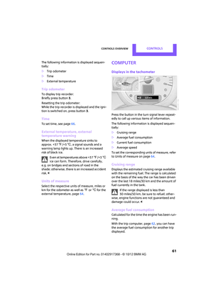
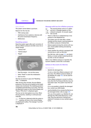
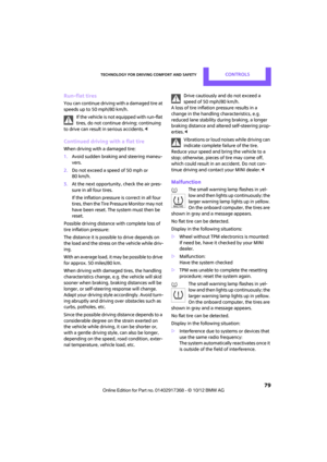
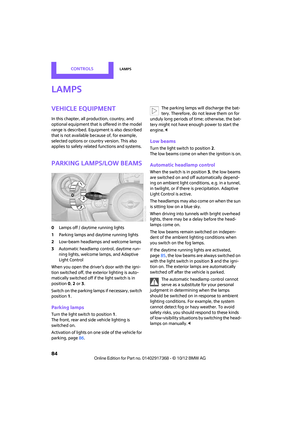
could result. To avoid possible injury or equip-
ment damage when replacing bulbs, observe
any instructions provided by the bulb manufac-
turer. <
Caring for headlamps, refer to page 221.
For any bulb replacement not described
below, contact a MINI dealer or a work-
shop that has specially trained personnel work-
ing in accordance with th e specifications of the
MINI manufacturer. <
For checking and adjusting headlamp aim,
please contact your MINI dealer. <
Light-emitting diodes LEDs
Light-emitting diodes installed behind translu-
cent lenses serve as the light sources for many of
the controls and displays in your vehicle. These
light-emitting diodes are related to conven-
tional laser diodes, and legislation de fines them
as Class 1 light-emitting diodes.
Do not remove the covers or expose the
eyes directly to the unfiltered light source
for several hours; otherw ise, this could cause
irritation of the retina. <
Headlamp glass lens
In cool or humid weather, condensation may
occur on the interiors of the headlamps. During
trips with the headlamps on, the condensation
disappears after a short time. The headlamps do
not need to be changed.
Do not remove the condensation from head-
lamps, despite driving with lights on, and if con-
densation increases, e.g., because of water
droplets, have this checked by your MINI dealer.
Xenon lamps
The service life of these bulbs is very long and
the probability of failure very low, provided that
they are not switched on and off an excessive
number of times. If a xenon lamp fails neverthe-
less, switch on the fog lamps and continue the
journey with great care, provided that local leg-
islation does not prohibit this.
Work on the xenon lighting system,
including lamp replacement, is only to be
carried out only by your MINI dealer. Due to high
voltage, there is a risk of fatal injury if work on
the xenon lamps is carried out improperly. <
Halogen low beams and high beams
H13 bulb, 60/55 watts
The H13 bulb is pressurized. Therefore,
wear safety glasses and protective gloves.
Otherwise, there is a risk of injury if the bulb is
damaged. <
Be careful when insta lling the cover; oth-
erwise, leaks could occur and cause dam-
age to the headlamp system. <
00320051004F004C00510048000300280047004C0057004C005200510003
Page 227 of 275
MOBILITYReplacing components
226
Accessing the lamp from the engine
compartment
The low-beam/high-beam bulb can be changed
from the engine compartment.
Removing the cover:
1.Press the tab.
2. Flip open the cover and take it out of the
holder.
Follow the same steps in reverse order to reat-
tach the cover.
Replacing the bulb
1. Turn the lamp counterclockwise, arrow 1,
and remove it, arrow 2.
2. Push on the catch, arrow 1, and disconnect
the connector, arrow 2. 3.
To insert the new bulb and replace the
cover, proceed in reverse order.
Turn signals, parking lamps, roadside
parking lamps, and fog lamps
Accessing the lamps via the wheel well
1Turn signal
2 Parking/roadside parking/fog lamps
Replacing a turn signal bulb
21 watt bulb, P21W, if necessary PY 21 W
1.Turn in the wheel.
2. Remove cover 1.
To do so, turn the cover counterclockwise.
3. Remove the inside cover.
To do so, turn the cover counterclockwise.
00320051004F004C00510048000300280047004C0057004C005200510003
Page 228 of 275

Replacing componentsMOBILITY
227
4.Unscrew the bulb counterclockwise.
5. To insert the new bulb and replace the cov-
ers, proceed in reverse order.
Replacing a parking/roadside parking
lamp bulb
5watt bulb, W5W
1.Turn in the wheel.
2. Remove cover 2.
To do so, turn the cover counterclockwise.
3. Unscrew the upper bulb counterclockwise.
4. To insert the new bulb and replace the
cover, proceed in reverse order.
Replacing a fog lamp bulb
H8 bulb, 35 watts
1.Turn in the wheel.
2. Remove cover 2.
To do so, turn the cover counterclockwise.
3. Detach the cable connector. 4.
Unscrew the lower bulb counterclockwise.
5. To insert the new bulb and replace the
cover, proceed in reverse order.
Side turn signals
5watt bulb, W5W
1.Open hood.
2. Squeeze clamping clip, arrows, and remove
bulb holder.
3. Unscrew bulb counterclockwise and
replace.
4. To insert the new bulb and replace the
cover, proceed in reverse order.
Side marker lamps
Have these bulbs replaced by your MINI dealer.
00320051004F004C00510048000300280047004C0057004C005200510003
Page 229 of 275

MOBILITYReplacing components
228
Tail lamps
Bulb P 21 W
MINI Countryman:
1Brake/tail lamp
2 Turn signal
3 Brake/tail lamp
4 Backup lamps
5 Backup lamps
MINI Paceman:
1 Brake light
2 Rear lamp
3 Turn signal
4 Backup lamps
Changing
All bulbs are integrated in a central bulb holder.
MINI Countryman:
1.Switch off the light and remove the infrared
remote control from the ignition lock.
2. Open the tailgate, 3.
Push the cover panel out from the rear of the
cargo area side trim panel and remove it.
4. Open emergency release for the fuel filler
flap, see page 200, and then push to the
side with the foam insert.
Ensure that the emergency release is not
damaged.
5. Disengage the bulb holder by pressing down
on the clamping clip, arrow 1.
6. Take out bulb holder and pull out cable,
arrow 2.
7. Exerting gentle pressure, turn bulb to the left
and remove.
8. To insert the new bulb and install the bulb
holder, proceed in reverse order. Ensure that
the lamp holder engages in all the fasteners.
9. Put foam insert in its original position and
install the emergency fuel flap release.
10. Install cover.
00320051004F004C00510048000300280047004C0057004C005200510003
Page 230 of 275

Replacing componentsMOBILITY
229
MINI Paceman:
1.Switch off the light and remove the infrared
remote control from the ignition lock.
2. Open the tailgate,
3. Remove the cover from the luggage com-
partment side panel.
4. Unlock the retaining element, arrow 1, by
turning it.
5. Remove the screws, arrow 2, using the hex
wrench from the vehicle document case.
6. Remove the tail lamp.
7. Disengage the bulb holder by pressing down
on the clamping clip, arrow 1.
8. Take out bulb holder and pull out cable,
arrow 2. 9.
Exerting gentle pressure, turn bulb to the left
and remove.
10. To insert the new bulb and install the bulb
holder, proceed in reverse order. Ensure that
the lamp holder engages in all the fasteners.
License plate lamps
5watt bulb, C5W
MINI Countryman:
MINI Paceman:
1.Using a screwdriver, push the lamp to the
left in the tab of the lamp housing, arrow 1.
2. Remove the lamp, arrow 2.
3. Replace the bulb.
4. Insert the lamp.
Center brake lamp
This lamp uses LED technology for operation. In
the event of a malfunction, contact your MINI
dealer or a workshop that has specially trained
personnel working in acco rdance with the spec-
ifications of your MINI manufacturer.
00320051004F004C00510048000300280047004C0057004C005200510003
Page 231 of 275

MOBILITYReplacing components
230
Repairing a flat tire
Safety measures in the event of a break-
down:
Park the vehicle as far as possible from moving
traffic and switch on the hazard warning flash-
ers.
Turn the steering wheel until the front wheels
are in the straight-ahead position and engage
the steering wheel lock. Engage the parking
brake and shift into 1st or reverse gear or place
the selector lever in position P.
All passengers should be outside the vehicle and
in a safe place, e.g. behind a guardrail.
Erect a warning triangle or warning flasher at the
appropriate distance if necessary. Comply with
all safety guidelines and regulations. <
In the event of a flat tire, different procedures
should be followed depending on the equip-
ment included in your vehicle:
> MINI Mobility Kit, refer to the following sec-
tion
> Run-flat tires, page 212
MINI Mobility Kit
The Mobility Kit is located under the left front
seat.
Preparations
Use of the MINI Mobility Kit may be ineffective if
the tire puncture measures approx. 1/8 in/4 mm
or more. Contact the nearest MINI dealer if the
tire cannot be made drivable with the Mobility
Kit.
Do not remove foreign bodies which have pen-
etrated the tire if possible.
Follow the instructions on using the Mobil-
ity Kit found on the compressor and the
sealant bottle. <
Remove the adhesive label for the speed limit
from the sealant bottle an d affix it to the steer-
ing wheel.
Sealant and compressor
1 Sealant bottle and adhesive label with speed
limit
2 Filling hose
Note the use-by date on the sealant bot-
tle. <
3 Holder for the sealant bottle
4 Compressor
5 Plug and cable for the socket in the vehicle
interior, page 101
6 Connection hose to connect the compressor
and sealant bottle or the compressor and
wheel
7 On/off switch
8 Pressure gauge for indi cating the tire infla-
tion pressure
9 Release button for reduci ng the tire inflation
pressure
Connector, cable and connection hose are
stored in the co mpressor housing.
00320051004F004C00510048000300280047004C0057004C005200510003
Page 232 of 275

Replacing componentsMOBILITY
231
Using the Mobility Kit
To repair a tire puncture with the Mobility Kit,
proceed as follows:
> Filling the tire with sealant.
> Distributing the sealant.
> Correct the tire inflation pressure.
Filling the tire with sealant
Proceed in the specifie d order; otherwise,
sealant may emerge under high pres-
sure. <
1. Shake the sealant bottle.
2. Pull the connecting hose 6 completely out of
the compressor housing and screw it onto
the connector of the sealant bottle. Make
sure that the hose is not kinked.
3. Insert the sealant bottle on the compressor
housing in an upright position.
4. Unscrew the dust cap from the valve of the
defective wheel and screw the filling hose 2
of the sealant bottle onto the valve.
5. Ensure that the compre ssor is switched off.
6. Insert the plug 5 into the lighter socket/
power socket in the vehicle interior,
page 101.
7. With the engine running:
Switch on the compre ssor and let run for
about 3 to 8 minutes in order to add the
sealant and to achieve an inflation pressure
of about 1.8 bar/26 psi. When adding sealant, the filling pres-
sure can temporarily increase up to
about 5 bar/73 psi. Do not switch off the
compressor during this phase. <
Do not run the compressor for longer
than 10 minutes; otherwise, the
device will overheat and possibly be dam-
aged. <
8. Switch off the compressor.
If an inflation pressure of 1.8 bar/26 psi is not
reached:
1. Unscrew the filling hose 2 from the wheel
and drive the vehicle forward and backward
approx. 33 ft/10 m to distribute the liquid
sealant in the tire evenly.
2. Inflate the tire again with the compressor.
If an inflation pressure of 1.8 bar/26 psi
still cannot be reached, then the tire is too
heavily damaged. Please contact the nearest
MINI dealer. <
Stowing Mobility Kit
1.Unscrew filler hose 2 of the sealant bottle
from the wheel.
2. Unscrew connecting hose of the
compressor 6 from the sealant bottle.
3. Connect the filler hose 2 of the sealant bot-
tle to the unoccupied connection on the
sealant bottle.
This prevents the rest of the sealant from
escaping from the bottle.
4. Wrap the empty sealant bottle in suitable
material to avoid dirtying the cargo area.
5. Stow Mobility Kit back in the vehicle.
Distributing the sealant
Immediately drive approx. 3.1 miles/5 km so
that the sealant evenly distributes itself.
Do not exceed speeds of 50 mph/
80 km/h.
If possible, do not drop below 10 mph/
20 km/h.<
00320051004F004C00510048000300280047004C0057004C005200510003