Page 265 of 294

@ Tips
The discharged battery must be properly
connected to the vehicle's electrical sys
tem. When jump starting or charg ing the
battery, never connect the negative
ground cable to the batte ry negat ive post
because the ba tte ry manager system must
be ab le to detect the battery's state of
charge. Always connect the negative
g round cab le to the negative ground pos t
of t he battery manager cont ro l unit.
Use of jumper cables
Make sure to connect the jumper coble
clomps in exactly the order described b elow!
Fi g. 193 Eng ine co mpar tment: Co nnecto rs fo r jum per
c ab les a nd c har ge r
F ig. 1 94 Jump start in g w ith t he ba ttery of a not her ve ·
hi cle :@ booster battery, @ disc harged veh icle battery
The procedure described below for connecting
jumper cables is intended to provide a jump
start for your veh icle .
Vehicle with di scharged battery :
~ Turn off lights and accessories, move leve r
of automatic transmission to N (Neutral) or P (Park) and set parking brake .
Emergency situ ation s 263
Connect POSITIVE(+) to POSITIVE(+ )
(red )
~ Remove the cover above the jump start con
nection .
~ Open the red cover on the positive pole
¢fig. 193 .
1. Connect one end of the red positive cable
on the
jump sta rt bolt c::;, fig. 194 (D
(Bolts under red cove r= "positive ") of the
vehicle to be sta rted @.
2 . Conne ct the othe r end to the pos itive ter -
mina l@ of the booster battery @.
Connect NEGATIVE (-) to NEGATIVE (-)
(black )
3. Co nnect one end o f the b lack neg ative c a
ble to the nega tive te rmi na l@ of the
booster battery @.
4 . Connect the other end to the
jump start
bolt @
(Bolts with hex head = "negative")
of the vehicle to be started @.
Starting the engine
~ Start t he e ngine o f the veh icle w ith the
booste r batte ry @ . Run the engine at a
moderate speed.
~ Start engine w ith d ischarged vehicle battery
® in the usual man ner .
~ If the eng ine fails to start : do not keep the
s tarter cran king for lo nger than 10 seconds .
Wait for about 30 seco nds and the n try
aga in.
~ With engi ne r unni ng , remove j umper cab les
from both vehicles in the exa ct
reverse o r
der .
~ Close the red cover on the positive pole .
T he b attery is vented to the o utside to p reven t
gases from en tering the veh icle in ter ior . Ma ke
s ur e that the j umper clamps a re well connect
ed with their
metal ports in full contact with
the batte ry term inals.
A WARNING
To avoid serious personal injury and dam
age to the vehicle, heed all warnings and
in structions of the jumper cable ma nufac-
turer . If i n dou bt, call for road servic e.
Ill>
Page 266 of 294

264 Emergency sit uat ions
-Jumper cables mus t be long enough so
that the vehicles do not touch.
- W hen connecting jumper ca bles, make
sure that they cannot get caught in any moving parts in the eng ine compart
ment.
- Do not bend over the batteries -danger
of chemical burns!
- The battery ce ll locking screws must be
tightened securely .
- Before you check anything in the engine
compartment, always read and heed all
WARNINGS
9 page 208, Engine com
partment.
(D Note
Improper hook-up of jumper cables can r u
in the generator.
- Always connect POSITIVE( +) to POSI
TIVE(+), and NEGATIVE( -) to NEGATIVE
( - ) ground post of the battery manager
control unit.
- Check that a ll screw plugs on the battery
cells are sc rewed in firmly. If not, tighten
plugs prior to connecting clamp on nega
tive battery term inal.
- Please note that the procedure for con
nect ing a jumper cable as described
above applies spec ifically to the case of
your vehicle being jump started . When
you are giv ing a jump start to a nothe r ve
hicle, do
not connect the negat ive (-) ca
ble to the negat ive (-) term inal on the
discharged battery @
9 fig. 194. In
stead, securely connect the negative(- )
cab le to e ither a solid metal component
that is firmly bolted to the engine bloc k
or to the engine block itse lf. If the bat
tery that is being charged does not vent
to the outside, escaping batte ry gas
could ignite and explode!
Emergency towing
with commercial tow
truck
General hints
Your Audi requires special handling for tow
ing.
T he following information is to be used by
commercial tow truck operators who know
how to operate their equipment safely.
- Ne ver tow your Audi , towing will cau se
damage to the engine and transmi ssion .
- Ne ver wrap th e safet y chains or winch ca
ble s around the brak e lines.
- To prevent unne cessar y damage, your Audi
must be tr an sp o rted with a flat bed tru ck.
- To load th e vehi cle on to the fl at bed, use
the towing l oop found in the ve hicle to ols
and atta ch to th e front or rea r anchorage
c:> page 265 and c:> page 265 .
& WARNING
= -
A vehicle being towed is not safe for pas
sengers. Never allow anyone to ride in a
vehicle being towed, for any reason.
Page 267 of 294

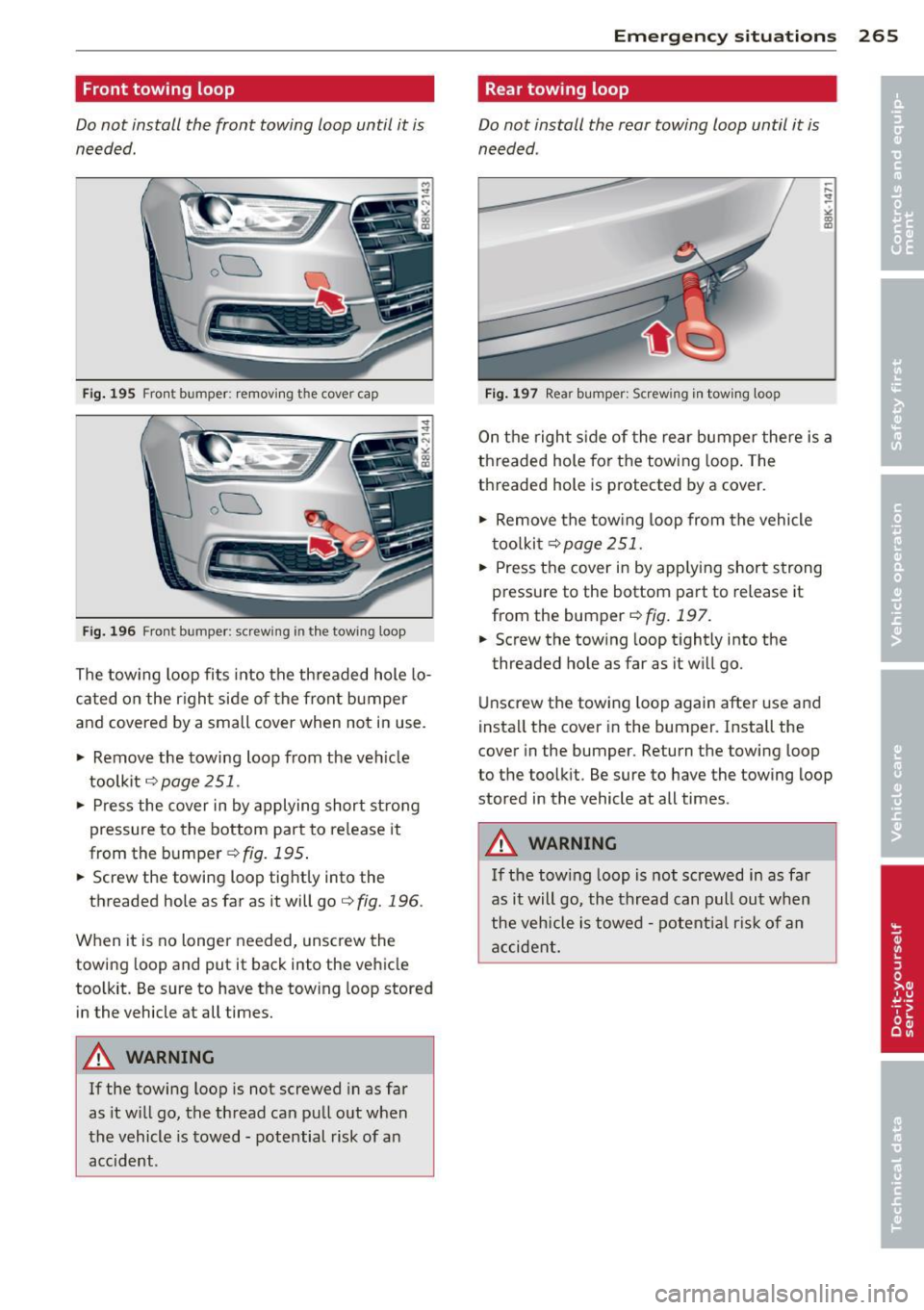
Front towing loop
Do not install the front towing loop until it is
needed.
ou
Fig . 195 Fro nt bumper : removing t he cover cap
ou
Fi g. 196 Front bumper: screw ing in t he tow ing loop
The tow ing loop fits into the th readed hole lo
cated on the r igh t side of the fron t bumper
and covered by a small cover when not in use .
"' Remove the towing loop from the veh icle
toolkit
c:::> page 251 .
"' Press the cover in by applying short st rong
pressure to the bottom part to re lease it
from the bumper
c:::> fig. 195 .
"' Screw the towing loop tight ly into the
threaded hole as far as it will go
c:::> fig. 196 .
When it is no longer needed, unscrew the
towing loop and put it back into the vehicle
too lkit. Be sure to have the tow ing loop stored
in the vehicle at all times.
A WARNING
If the towing loop is not screwed in as far
as it w ill go, the thread can pull out when
the vehicle is towed - potential risk of an
acc ident.
Emergenc y situ ation s 265
Rear towing loop
Do not install the rear towing loop until it is
needed .
Fig . 1 97 Rea r bumper: Screw ing in tow ing loop
On the right s ide of the rear bumper there is a
th readed hole for the towing loop . The
threaded hole is protected by a cover .
"' Remove the tow ing loop from the vehicle
t oo lkit
c:::> page 251.
"' Press the cover in by app lying short strong
pressure to the bottom part to release it
from the bumper
c:::> fig. 197.
"' Screw the tow ing loop tightly into the
threaded hole as far as it w ill go.
Unscrew the towing loop again after use and
insta ll the cover in the bumper. Install the
cover in the bumper. Return the towing loop
to the toolkit. Be sure to have the towing loop
stored in the vehicle at all times .
A WARNING
If the towing loop is not screwed in as far
as it will go, the thread can pull out when
the veh icle is towed -potent ia l risk o f an
accident.
Page 268 of 294

266 Emergency situations
loading the vehicle onto a flat bed truck
Fig . 19 8 Vehicle o n flat bed tr uck
Front hook up
• Align the ve hicle w ith the centerline of t he
ca r ca rr ier ramp .
• Attach the w inch hook to the front towline
eye previou sly insta lled .
Rear hook up
• Align the ve hicle w ith the centerline of t he
car ca rrier ramp.
• Attach the w inch hook to the rear towline
eye previously insta lled.
@ Tips
Check carefully to make sure the hook- up
is se cure befor e moving th e ca r u p the flat·
bed truck ramp.
Lifting vehicle
lifting with workshop hoist and with
floor jack
The vehicle may only be li~ed at the lifting
points illustrated.
Fi g. 199 Fro nt lift ing po int
:g 0 N
" O> a,
Fig. 20 0 Rear lifting point
• Read and heed WARNING q .&.
• Locate lifting poi nts q fig. 199 and
q fig. 200 .
• Adjust lifting arms of wo rks hop ho ist o r
floor ja ck to ma tc h veh icle lift ing poi nts .
• Insert a rubber pad be tween the floo r jack/
workshop hoist and t he lift ing points.
If you mu st lift your vehi cle with a floor jack
to work underneath, be sure the vehicle is
safely supported on stand s intended for this
purpose.
Front lifting point
T he lift ing po in t is loca ted o n the floo r pan re
i nforcemen t abo ut a t the same leve l as the
jack mounting point
q fig. 199. Do not lift
the vehicle at the vertical sill reinforcement .
Rear lifting point
T he lifti ng poi nt is located o n the vert ic al rei n
f o rcement of the lower s il l for the onboard
jac k
c> fig. 200 .
lifting with vehicle jack
Refer to c:> page 2 55.
A WARNING
= -
-To r educe the risk of ser ious injury and
veh icle damage.
- Always lift the vehicle only at the spe
cia l workshop hoist and floor jac k lift
po ints illustrated
c> fig. 199 and
c> fig. 200.
- Failure t o lift the vehicle at these
po ints could cause the vehicle to tilt or
fall from a lift if there is a change i n ve-
hicle weight dist ribution and balance.
~
Page 269 of 294

This might happen, for examp le, w hen
heavy components such as the engine
b lock or transmiss io n are removed .
- When removing heavy components like
these, anchor vehicle to ho ist o r add cor
responding weig hts to mai nta in the cen
ter of g ravity. Othe rwise, the veh icle
m ight tilt o r slip off t he hois t, causi ng
serious p ersona l injury.
(I) Note
- Be awa re of th e fo llowing po ints befo re
li fting the vehicle:
- The vehicle should never be lifted or
jacked up from underneath the engine oil pan , the transmission housing , the
front or rear axle or the body s ide
members. This could lead to ser ious
damage.
- To avoid damage to the underbody or
chassis frame , a rubber pad must be
inserted between the floor jack and
the lift points .
-Before driv ing over a workshop hoist,
check that the vehicle weight does not
exceed the permi ssible lifting capacity
of the hoi st.
- Before driv ing over a workshop hoist,
ensure that there i s sufficient clear
ance between the hoist and low parts
of the vehicle.
Emergency situations 267
•
•
Page 270 of 294

268 General information
General information Explanation of
technical data
Some of the technical data listed in this man
ual requires further explanation .
The technical data for your vehicle is listed in
the charts starting on
r:::> page 2 70. This sec
tion provides general information, notes and restrictions which apply to this data .
Vehicle identification
The key data is given on the vehicle identifica
tion number (VIN) plate and the vehicle data
sticker.
Fig. 201 Veh icle Ide ntific atio n Number (VlN) p late: lo
cation on driver 's sid e das h panel
Fig. 202 The vehicle identi fication label -inside the
luggage co mpa rtmen t
The Vehicle Identification Number (VIN)
is located on the driver's side so that it is visi
ble from the outside through the windshield
r:::> fig . 201 . You can also display the Vehicle
Identification Number of your vehicle in the
radio or in the MM!*. Select :
!CAR ! function
button
> Vehicle ID number (VIN) or select:
ICARI function button > Car systems control
button
> Servicing & checks > VIN number . The
vehicle identification label
is located in the luggage compartment near
the battery .
The label¢
fig. 202 shows the following vehi
cle data :
(D Production control No .
@ Vehicle identification No.
® Type code number
@ Type designation/engine output in Kilo-
watts
® Engine and transmission code letter
@ Paint No./Interior
(f) Optional equipment No.'s
Vehicle data 2 to 7 are also found in your War
ranty
& Maintenance booklet.
The safety compliance sticker
is you r assurance that your new vehicle com
plies with all applicable Federal Motor Vehicle
Safety Standards which were in effect at the
time the vehicle was manufactured . You can
find this sticker on the left door jamb.
It
shows the month and year of production and
the ve hicle ident ification number of your vehi
cle (perforation) as well as the Gross Vehicle
Weight Rating (GVWR) and the Gross Axle
Weight Rating (GAWR) .
The high voltage warning label
is located on the lock carr ier .
The spark ignition system complies with
the Canadian standard ICES-002.
Weights
Gross Vehicle Weight Rating
The Gross Vehicle Weight Rating (GVWR), and
the Gross Axle Weight Rating (GAWR) for
front and rear are Listed on a sticker on the
left door jamb.
The Gross Vehicle Weight Rating includes the
weight of the basic vehicle plus full fuel tank,
oi l and coolant, plus maximum load, wh ich in
cludes passenger weight (150 lbs./68 kg per
Ill>
Page 271 of 294

designated seating position) and luggage
weight~&. .
Gros s Axle W eight Rating
The G ross Axle Weight Rating is the maximum
l oad that can be applied at each axle of the
vehicle
q .&. .
Vehicle capacit y weight
The vehicle capac ity we ight (max. load) is list
ed on the driver 's side 8-p illar.
Roof weight
The maximum permissible roof weight is
19 8 lb s. (9 0 kg ). The roof weight is made up
of the weight of the roof rack system and the
weight of the object be ing transported
q page 64, Loading the roof rack .
..&, WARNING
- T he actual Gross Axle Weight Rat ing at
the front and rea r axles sho uld not ex
ceed the permissible weights, and their
combination must not exceed the Gross
Vehicle Weight Rating.
- Exceeding permissib le we ight ratings can
result in vehicle damage, accidents and
persona l injury.
Q) Note
- The vehicle capacity weight figures app ly
when the load is distributed evenly in the
vehicle (passengers and luggage). When
transporting a heavy load in the luggage
compartment, carry the load as near to
the rear axle as possible so that the veh i
cle's handling is not impaired .
- Do not exceed the maximum permissible
axle loads or the maximum gross vehicle
weight. Always remember that the vehi
cle's handling will be affected by the ex
tra load. Therefore, adjust your speed ac
cord ingly.
- Always observe local regu lations.
-
G ene ral in formation 269
Dimensions
The specifications refer to the basic model.
Differences may occur depending on the mod
el type and options ordered, for example, tire
sizes.
(D Note
When driving up steep ramps, on rough roads, over curbs, etc. it is important to re
member that some parts of your vehicle,
such as spoilers or exhaust system compo nents, may be close to the ground . Be
careful not to damage them .
•
•
Page 272 of 294

270 Data
Data
211 hp, 2.0 liter 4-cyl. engine
Engine data
Maximum output SAE net
Maximum torque SAE net
No. of cylinders
Displacement
Stroke
Bore
Compression ratio
Fuel
Dimensions (approx .)
Length (with licence plate bracket)
Width (with outside mirrors folded)
He ight (unloaded)
T urning circle diameter (curb to curb)
Capacities (approx.)
Fuel tank
h p@rpm
l b-ft@rpm
CID (cm
3 )
in (mm)
i n (mm)
211 @4300-6000
258@ 1500-4200
4
121 (1984)
3.65 (92 .8)
3 .25 (82 .5)
9.6: 1
Premium unleaded (91 AKI ) Recommended for
maximum engine performance . Further details
¢ page 210, Gasoline
Bio-ethanol (E85 ) Vehicles with flexible fuel en
gines may be operated with bio-ethanol fuels
(E85) or with premium unleaded gasoline
(91
AKI) . Further details~ page 211, Ethanol fuel
(Bio-ethanol).
in (mm)
in (mm)
in (mm)
ft (m)
185.1 (4701)
56.2 (1427)
37.7 (11.5)
- Total capacity gal (liters)
-------------
- Reserve (of total capacity)
Wind
shield and headlight* wa sher fluid container
Engine oil
with filter change gal (liters)
quarts (liters)
q
uarts (lite rs)
1.8-2.4
(7 -9)
4 .8 (4 .5)
4 .9 (4 .6)