Page 73 of 96

PERIODIC MAINTENANCE AND ADJUSTMENT
6-26
2
3
4
567
8
9
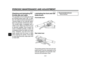
EAU23213
Checking and lubricating the
centerstand and sidestand The operation of the centerstand and
sidestand should be checked before
each ride, and the pivots and met-
al-to-metal contact surfaces should be
lubricated if necessary.
WARNING
EWA10741
If the centerstand or sidestand does
not move up and down smoothly,
have a Yamaha dealer check or re-
pair it. Otherwise, the centerstand or
sidestand could contact the ground
and distract the operator, resultingin a possible loss of control.
EAU23272
Checking the front fork The condition and operation of the front
fork must be checked as follows at the
intervals specified in the periodic main-
tenance and lubrication chart.
To check the condition
Check the inner tubes for scratches,
damage and excessive oil leakage.
To check the operation1. Place the vehicle on a level sur- face and hold it in an upright posi-
tion. WARNING! To avoid injury,
securely support the vehicle so
there is no danger of it falling
over.
[EWA10751]
2. While applying the front brake, push down hard on the handlebars
several times to check if the front
fork compresses and rebounds
smoothly.
Recommended lubricant:Lithium-soap-based grease
59C-9-E0.book 26 ページ 2011年9月11日 日曜日 午前9時27分
Page 74 of 96

PERIODIC MAINTENANCE AND ADJUSTMENT
6-27
1
2
3
4
56
7
8
9
NOTICE
ECA10590
If any damage is found or the front
fork does not operate smoothly,
have a Yamaha dealer check or re-pair it.
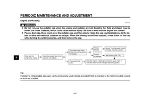
EAU45511
Checking the steering Worn or loose steering bearings may
cause danger. Therefore, the operation
of the steering must be checked as fol-
lows at the intervals specified in the pe-
riodic maintenance and lubrication
chart.1. Place the vehicle on the center- stand. WARNING! To avoid inju-
ry, securely support the vehicle
so there is no danger of it falling
over.
[EWA10751]
2. Hold the lower ends of the front fork legs and try to move them for-
ward and backward. If any free
play can be felt, have a Yamaha
dealer check or repair the steering.
EAU23291
Checking the wheel bearings The front and rear wheel bearings must
be checked at the intervals specified in
the periodic maintenance and lubrica-
tion chart. If there is play in the wheel
hub or if the wheel does not turn
smoothly, have a Yamaha dealer check
the wheel bearings.
59C-9-E0.book 27 ページ 2011年9月11日 日曜日 午前9時27分
Page 75 of 96

This model is equipped with a VRLA
(Valve Regulated")
PERIODIC MAINTENANCE AND ADJUSTMENT
6-28
2
3
4
567
8
9
EAU52042
Battery The battery is located under front stor-
age compartment A. (See page 3-20.)
This model is equipped with a VRLA
(Valve Regulated Lead Acid) battery.
There is no need to check the electro-
lyte or to add distilled water. However,
the battery lead connections need to be
checked and, if necessary, tightened.
WARNING
EWA10760
Electrolyte is poisonous and
dangerous since it contains sul-
furic acid, which causes severe
burns. Avoid any contact with
skin, eyes or clothing and al-
ways shield your eyes when
working near batteries. In case
of contact, administer the fol-
lowing FIRST AID.
EXTERNAL: Flush with plentyof water.
INTERNAL: Drink large quan- tities of water or milk and im-
mediately call a physician.
EYES: Flush with water for 15 minutes and seek prompt medical attention.
Batteries produce explosive hy-
drogen gas. Therefore, keep
sparks, flames, cigarettes, etc.,
away from the battery and pro-
vide sufficient ventilation when
charging it in an enclosed
space.
KEEP THIS AND ALL BATTER-
IES OUT OF THE REACH OFCHILDREN.
To access the battery 1. Remove panel B. (See page 6-8.)
2. Open the front storage compart- ment A. (See page 3-20.)
3. Pull the storage compartment out- ward, then remove it. 4. Remove the front storage com-
partment A by removing the
screws.
1. Storage compartment
1. Screw
2. Front storage compartment A
11
1
2
59C-9-E0.book 28 ページ 2011年9月11日 日曜日 午前9時27分
Page 76 of 96

PERIODIC MAINTENANCE AND ADJUSTMENT
6-29
1
2
3
4
56
7
8
9To charge the battery
Have a Yamaha dealer charge the bat-
tery as soon as possible if it seems to
have discharged. Keep in mind that the
battery tends to discharge more quickly
if the vehicle is equipped with optional
electrical accessories.
NOTICE
ECA16521
To charge a VRLA (Valve Regulated
Lead Acid) battery, a special (con-
stant-voltage) battery charger is re-
quired. Using a conventional batterycharger will damage the battery. To store the battery
1. If the vehicle will not be used for more than one month, remove the
battery, fully charge it, and then
place it in a cool, dry place.
NOTICE: When removing the
battery, be sure the key is
turned to “OFF”, then discon-
nect the negative lead before
disconnecting the positive
lead.
[ECA16302]
2. If the battery will be stored for more than two months, check it at least
once a month and fully charge it if
necessary.
3. Fully charge the battery before in- stallation. NOTICE: When install-
ing the battery, be sure the key
is turned to “OFF”, then con-
nect the positive lead before
connecting the negative
lead.
[ECA16840]
4. After installation, make sure that the battery leads are properly con-
nected to the battery terminals.
NOTICE
ECA16530
Always keep the battery charged.
Storing a discharged battery can
cause permanent battery damage.
1. Negative battery lead (black)
2. Positive battery lead (red)
3. Battery
2
3 1
59C-9-E0.book 29 ページ 2011年9月11日 日曜日 午前9時27分
Page 77 of 96

PERIODIC MAINTENANCE AND ADJUSTMENT
6-30
2
3
4
567
8
9
EAU23633
Replacing the fuses
The main fuse box and the fuse box,
which contains the fuses for the individ-
ual circuits, are located under panel A.
(See page 6-8.)
If a fuse is blown, replace it as follows.1. Turn the key to “OFF” and turn off the electrical circuit in question.
2. Remove the blown fuse, and then install a new fuse of the specified amperage.
WARNING! Do not
use a fuse of a higher amperage
rating than recommended to
avoid causing extensive dam-
age to the electrical system and
possibly a fire.
[EWA15131]
3. Turn the key to “ON” and turn on the electrical circuit in question to
check if the device operates.
4. If the fuse immediately blows again, have a Yamaha dealer
check the electrical system.
1. Main fuse
2. Spare main fuse
3. Main fuse box cover
1
2
3
1. Spare fuse
2. Parking lighting fuse
3. Signaling system fuse
4. Ignition fuse
5. Backup fuse
6. Radiator fan fuse
7. Fuel injection system fuse
8. Headlight fuse
9. Spare fuse
9 3
4
56
7 8
21
Specified fuses:
Main fuse: 40.0 A
Headlight fuse: 20.0 A
Signaling system fuse:
15.0 A
Ignition fuse: 7.5 A
Radiator fan fuse: 15.0 A
Fuel injection system fuse:
7.5 A
Parking lighting fuse: 10.0 A
Backup fuse: 7.5 A
59C-9-E0.book 30 ページ 2011年9月11日 日曜日 午前9時27分
Page 78 of 96

PERIODIC MAINTENANCE AND ADJUSTMENT
6-31
1
2
3
4
56
7
8
9
EAU52230
Replacing the headlight bulb This model is equipped with a halogen
bulb headlights. If the headlight bulb
burns out, replace it as follows.NOTICE
ECA10650
Take care not to damage the follow-
ing parts:
Headlight bulb
Do not touch the glass part of
the headlight bulb to keep it free
from oil, otherwise the transpar-
ency of the glass, the luminosity
of the bulb, and the bulb life will
be adversely affected. Thor-
oughly clean off any dirt and fin-
gerprints on the headlight bulb
using a cloth moistened with al-
cohol or thinner.
Headlight lens
Do not affix any type of tinted
film or stickers to the headlight
lens.
Do not use a headlight bulb of awattage higher than specified. 1. Remove panel A. (See page 6-8.)
2. Remove the headlight bulb cover.
3. Disconnect the headlight coupler,
and then remove the burnt-out
bulb by turning it counterclock-
wise. 4. Install a new bulb by turning it
clockwise.
5. Connect the headlight coupler.
6. Install the headlight bulb cover.
7. Install the panel.
8. Have a Yamaha dealer adjust the headlight beam if necessary.
1. Do not touch the glass part of the bulb.
1. Headlight bulb cover
1
1
1. Headlight coupler
2. Headlight bulb
1
2
59C-9-E0.book 31 ページ 2011年9月11日 日曜日 午前9時27分
Page 79 of 96
PERIODIC MAINTENANCE AND ADJUSTMENT
6-32
2
3
4
567
8
9
EAU24181
Tail/brake light This model is equipped with an
LED-type tail/brake light.
If the tail/brake light does not come on,
have a Yamaha dealer check it.
EAU52320
Replacing a front turn signal
light bulb 1. Place the scooter on the center-
stand.
2. Remove the socket (together with the bulb) by turning it counter-
clockwise.
3. Remove the burnt-out bulb by pushing it in and turning it counter-
clockwise. 4. Insert a new bulb into the socket,
push it in, and then turn it clock-
wise until it stops.
5. Install the socket (together with the bulb) by turning it clockwise.1. Turn signal light bulb socket
1
1. Turn signal light bulb
2. Turn signal light bulb socket
1 2
59C-9-E0.book 32 ページ 2011年9月11日 日曜日 午前9時27分
Page 80 of 96
PERIODIC MAINTENANCE AND ADJUSTMENT
6-33
1
2
3
4
56
7
8
9
EAUT1330
Rear turn signal light bulbIf a rear turn signal light does not come
on, have a Yamaha dealer check the
electrical circuit or replace the bulb.
EAU24313
Replacing the license plate
light bulb 1. Remove the license plate light unitby removing the screws.
2. Remove the license plate light bulb socket (together with the bulb) by
pulling it out. 3. Remove the burnt-out bulb by pull-
ing it out.
4. Insert a new bulb into the socket.
5. Install the socket (together with the bulb) by pushing it in.
6. Install the license plate light unit by installing the screws.1. Screw
1
1. License plate light unit
2. License plate light bulb socket
1 2
59C-9-E0.book 33 ページ 2011年9月11日 日曜日 午前9時27分