Page 33 of 96

INSTRUMENT AND CONTROL FUNCTIONS
3-18
234
5
6
7
8
9
EAU13433
Catalytic converter This model is equipped with a catalytic
converter in the exhaust system.
WARNING
EWA10862
The exhaust system is hot after op-
eration. To prevent a fire hazard or
burns:
Do not park the vehicle near
possible fire hazards such as
grass or other materials that
easily burn.
Park the vehicle in a place
where pedestrians or children
are not likely to touch the hot
exhaust system.
Make sure that the exhaust sys-
tem has cooled down before do-
ing any maintenance work.
Do not allow the engine to idle
more than a few minutes. Long
idling can cause a build-up ofheat.
NOTICE
ECA10701
Use only unleaded gasoline. The use
of leaded gasoline will cause unre-
pairable damage to the catalytic
converter.
EAU13932
Seat To open the seat1. Place the scooter on the center- stand.
2. Insert the key into the main switch, and then turn it counterclockwise
to “OPEN”.TIPDo not push inward when turning thekey.
3. Fold the seat up.1. Open.
1
59C-9-E0.book 18 ページ 2011年9月11日 日曜日 午前9時27分
Page 34 of 96
INSTRUMENT AND CONTROL FUNCTIONS
3-19
1
23
4
5
6
7
8
9To close the seat
1. Fold the seat down, and then push it down to lock it in place.
2. Remove the key from the main switch if the scooter will be left un-
attended.
TIPMake sure that the seat is properly se-cured before riding.
EAU14270
Adjusting the rider backrest The rider backrest can be adjusted to
the three different positions shown.
Adjust the backrest as follows.1. Open the seat. (See page 3-18.)
2. Remove the backrest bolts. 3. Slide the backrest forward or back-
ward to the desired position.
4. Install and securely tighten the backrest bolts.
5. Close the seat.1. Rider backrest
1
1. Rider backrest
2. Bolt
1
2
59C-9-E0.book 19 ページ 2011年9月11日 日曜日 午前9時27分
Page 35 of 96

INSTRUMENT AND CONTROL FUNCTIONS
3-20
234
5
6
7
8
9
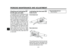
EAU46300
Helmet holder The helmet holder is located under the
seat. A helmet holding cable is provid-
ed beside the owner’s tool kit to secure
a helmet to the helmet holder.
To secure a helmet to the helmet
holder1. Open the seat. (See page 3-18.)
2. Pass the helmet holding cable through the buckle on the helmet
strap as shown, and then hook the
cable loop over the helmet holder.
3. Make sure the helmet holding ca- ble is not touching the shaded pro- jection, and securely close the
seat. WARNING! Never ride with
a helmet attached to the helmet
holder, since the helmet may hit
objects, causing loss of control
and possibly an accident.
[EWA10161]
To release the helmet from the hel-
met holder
Open the seat, remove the helmet
holding cable from the helmet holder
and the helmet, and then close the
seat.
EAU52221
Storage compartments Front storage compartment A
To open the storage compartment, pull
the lid as shown. WARNING! Do not
store heavy items in this compart-
ment.
[EWA11161]
To close the storage compartment,
push the lid into the original position.
1. Shaded projection
2. Helmet holding cable
3. Helmet holder
3
1
2
1. Front storage compartment A
1
59C-9-E0.book 20 ページ 2011年9月11日 日曜日 午前9時27分
Page 36 of 96

INSTRUMENT AND CONTROL FUNCTIONS
3-21
1
23
4
5
6
7
8
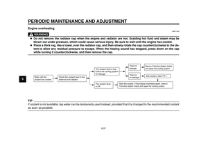
9Front storage compartment B
To open the storage compartment
when it is locked, insert the key in the
lock, turn it clockwise, and then pull on
the lever while pushing the lever up. To open the storage compartment
when it is unlocked, simply pull on the
lever while pushing the lever up.
To close the storage compartment,
push the lid into the original position.
To lock the storage compartment, push
the lid into the original position, insert
the key in the lock, turn it counterclock-
wise, and then remove it.
Rear storage compartment
A helmet can be stored in the rear stor-
age compartment under the seat. (See
page 3-18.) To store a helmet in the
rear storage compartment, place the
helmet upside down with the front fac-
ing the left side.
NOTICE: Keep the
following points in mind when using
the storage compartment. Since the storage compartment accumulates
heat when exposed to the sun and/
or the engine heat, do not store any-
thing susceptible to heat, consum-
ables or flammable items inside it.
To avoid humidity from spreading
through the storage compartment,
wrap wet articles in a plastic bag be-
fore storing them in the compart-
ment. Since the storage
compartment may get wet while the
scooter is being washed, wrap any
articles stored in the compartment
in a plastic bag. Do not keep any-
thing valuable or breakable in the
storage compartment. Do not leave
the seat open for an extended period
of time, otherwise the light may
cause the battery to discharge.
[ECA16082]
NOTICE:
The shaded area is not a
storage compartment. To prevent
damaging the seat hinges, do not
place any items in this area.
[ECA16091]
1. Unlock.
2. Front storage compartment B
3. Storage compartment opening lever
1 2
3
59C-9-E0.book 21 ページ 2011年9月11日 日曜日 午前9時27分
Page 37 of 96
INSTRUMENT AND CONTROL FUNCTIONS
3-22
234
5
6
7
8
9
TIP
Some helmets cannot be stored in
the rear storage compartment be-
cause of their size or shape.
Do not leave your scooter unat-tended with the seat open.
NOTICE
ECA11100
Do not leave the rider seat open for
an extended period of time, other-
wise the light may cause the batteryto discharge.
WARNING
EWA16120
Do not exceed the following loadinglimits:
Front storage compartment A:
0.15 kg (0.3 lb)
Front storage compartment B:
1 kg (2 lb)
Rear storage compartment: 5 kg
(11 lb)
Maximum load for the vehicle:198 kg (437 lb)
EAU52211
Windshield To suit the rider’s preference, the wind-
shield height can be changed to one of
two positions.
To adjust the windshield height
1. Remove the screw access covers by removing the quick fasteners.
1. Rear storage compartment
2. Shaded area
1
2
1. Windshield
1
59C-9-E0.book 22 ページ 2011年9月11日 日曜日 午前9時27分
Page 38 of 96
INSTRUMENT AND CONTROL FUNCTIONS
3-23
1
23
4
5
6
7
8
92. Remove the windshield by remov-
ing the screws.
3. Remove the rubber caps. 4. Install the rubber caps in the de-
sired position.
5. Install the windshield to the de- sired position by installing the
screws. 6. Tighten the screws to the specified
torque. WARNING! A loose wind-
shield could cause an accident.
Be sure to tighten the screws to
the specified torque.
[EWA15510]
7. Place the screw access covers, and then install the quick fasten-
ers.
1. Quick fastener
2. Screw access cover
1. Screw1
2
11
1
1. Rubber cap
1. Rubber cap
1
1
1
1
1. ScrewTightening torque:Windshield screw:
10 Nm (1.0 m·kgf, 7.2 ft·lbf)
1
1
59C-9-E0.book 23 ページ 2011年9月11日 日曜日 午前9時27分
Page 39 of 96

INSTRUMENT AND CONTROL FUNCTIONS
3-24
234
5
6
7
8
9
EAU39671
Rear view mirrors The rear view mirrors of this vehicle can
be folded forward or backward for park-
ing in narrow spaces. Fold the mirrors
back to their original position before
riding.
WARNING
EWA14371
Be sure to fold the rear view mirrors
back to their original position beforeriding.
EAU46021
Shock absorber assembly
WARNING
EWA10221
This shock absorber assembly con-
tains highly pressurized nitrogen
gas. Read and understand the fol-
lowing information before handling
the shock absorber assembly.
Do not tamper with or attempt to
open the cylinder assembly.
Do not subject the shock ab-
sorber assembly to an open
flame or other high heat source.
This may cause the unit to ex-
plode due to excessive gas
pressure.
Do not deform or damage the
cylinder in any way. Cylinder
damage will result in poor
damping performance.
Do not dispose of a damaged or
worn-out shock absorber as-
sembly yourself. Take the shock
absorber assembly to a Yamahadealer for any service.
1. Screw access cover
1
1. Parking position
2. Riding position
1
1 2
2 1
1
59C-9-E0.book 24 ページ 2011年9月11日 日曜日 午前9時27分
Page 40 of 96

INSTRUMENT AND CONTROL FUNCTIONS
3-25
1
23
4
5
6
7
8
9
EAU15305
Sidestand The sidestand is located on the left side
of the frame. Raise the sidestand or
lower it with your foot while holding the
vehicle upright.TIPThe built-in sidestand switch is part of
the ignition circuit cut-off system, which
cuts the ignition in certain situations.
(See the following section for an expla-
nation of the ignition circuit cut-off sys-tem.)
WARNING
EWA10241
The vehicle must not be ridden with
the sidestand down, or if the side-
stand cannot be properly moved up
(or does not stay up), otherwise the
sidestand could contact the ground
and distract the operator, resulting
in a possible loss of control.
Yamaha’s ignition circuit cut-off
system has been designed to assist
the operator in fulfilling the respon-
sibility of raising the sidestand be-
fore starting off. Therefore, check
this system regularly and have aYamaha dealer repair it if it does not
function properly.
EAU45051
Ignition circuit
cut-off system The ignition circuit cut-off system (com-
prising the sidestand switch and brake
light switches) has the following func-
tions.
It prevents starting when the side-
stand is up, but neither brake is ap-
plied.
It prevents starting when either
brake is applied, but the sidestand
is still down.
It cuts the running engine when the
sidestand is moved down.
Periodically check the operation of the
ignition circuit cut-off system according
to the following procedure.
59C-9-E0.book 25 ページ 2011年9月11日 日曜日 午前9時27分