Page 25 of 96

INSTRUMENT AND CONTROL FUNCTIONS
3-10
234
5
6
7
8
9
from the ambient temperature. Pushing
the right set button switches the ambi-
ent temperature display to the average
fuel consumption and instantaneous
fuel consumption modes.
Average fuel consumption mode
The average fuel consumption display
can be set to either “AVE_ _._ km/L” or
“AVE_ _._ L/100 km” (except for the
UK).
For the UK only:
The average fuel consumption is dis-
played “AVE_ _._ MPG”.
This display shows the average fuel consumption since it was last reset.
When the display is set to “AVE_
_._ km/L”, the average distance
that can be traveled on 1.0 L of fuel
is shown.
When the display is set to “AVE_
_._ L/100 km”, the average
amount of fuel necessary to travel
100 km is shown.
For the UK only: When the display
is set to “AVE_ _._ MPG”, the av-
erage distance that can be trav-
eled on 1.0 Imp.gal of fuel is
shown.
To switch between the average fuel
consumption displays, push the left set
button for one second when one of the
displays is shown (except for the UK).
To reset the average fuel consumption
display, select it by pushing the right set
button, and then push the right set but-
ton for at least one second.
TIPAfter resetting an average fuel con-
sumption display, “_ _._” is shown for
that display until the vehicle has trav-eled 1 km (0.6 mi). Instantaneous fuel consumption mode
The instantaneous fuel consumption
display can be set to either “km/L” or “L/
100 km” (except for the UK).
For the UK only:
The instantaneous fuel consumption is
displayed “MPG”.
When the display is set to “km/L”,
the distance that can be traveled
on 1.0 L of fuel under the current
riding conditions is shown.
When the display is set to “L/100
km”, the amount of fuel necessary
to travel 100 km under the current
riding conditions is shown.
1. Average fuel consumption display
1
1. Instantaneous fuel consumption display
1
59C-9-E0.book 10 ページ 2011年9月11日 日曜日 午前9時27分
Page 26 of 96

INSTRUMENT AND CONTROL FUNCTIONS
3-11
1
23
4
5
6
7
8
9
For the UK only: The distance that
can be traveled on 1.0 Imp.gal of
fuel under the current riding condi-
tions is shown.
TIPIf traveling at speeds under 10 km/h(6.0 mi/h), “_ _._” is displayed.
Self-diagnosis device
This model is equipped with a self-diag-
nosis device for various electrical cir-
cuits.
If a problem is detected in any of those
circuits, the engine trouble warning light
comes on and the display indicates an
error code.
If the display indicates any error codes,note the code number, and then have a
Yamaha dealer check the vehicle.
The self-diagnosis device also detects
problems in the imm
obilizer system cir-
cuits.
If a problem is detected in any of the im-
mobilizer system circuits, the immobi-
lizer system indicator light flashes and
the display indicates an error code.
TIPIf the display indicates error code 52,
this could be caused by transponder in-
terference. If this error code appears,try the following.
1. Use the code re-registering key to start the engine.TIPMake sure there are no other immobi-
lizer keys close to the main switch, and
do not keep more than one immobilizer
key on the same key ring! Immobilizer
system keys may cause signal interfer-
ence, which may prevent the enginefrom starting.
2. If the engine starts, turn it off and try starting the engine with the
standard keys. 3. If one or both of the standard keys
do not start the engine, take the
vehicle, the code re-registering
key and both standard keys to a
Yamaha dealer and have the stan-
dard keys re-registered.
NOTICE
ECA11590
If the display indicates an error
code, the vehicle should be checked
as soon as possible in order to avoidengine damage.
1. Error code display
1
59C-9-E0.book 11 ページ 2011年9月11日 日曜日 午前9時27分
Page 27 of 96
INSTRUMENT AND CONTROL FUNCTIONS
3-12
234
5
6
7
8
9
EAU12331
Anti-theft alarm (optional) This model can be equipped with an
optional anti-theft alarm by a Yamaha
dealer. Contact a Yamaha dealer for
more information.
EAU1234A
Handlebar switches LeftRight
EAU12360
Pass switch “PASS”
Press this switch to flash the headlight.
EAU12400
Dimmer switch “ / ”
Set this switch to “ ” for the high
beam and to “ ” for the low beam.
EAU12460
Turn signal switch “ / ”
To signal a right-hand turn, push this
switch to “ ”. To signal a left-hand
turn, push this switch to “ ”. When re-
leased, the switch returns to the center
1. Pass switch “PASS”
2. Dimmer switch “ / ”
3. Turn signal switch “ / ”
4. Horn switch “ ”
1
2
3
4
1. Engine stop switch “ / ”
2. Hazard switch “ ”
3. Start switch “ ”
1
2
3
59C-9-E0.book 12 ページ 2011年9月11日 日曜日 午前9時27分
Page 28 of 96

INSTRUMENT AND CONTROL FUNCTIONS
3-13
1
23
4
5
6
7
8
9position. To cancel the turn signal
lights, push the switch in after it has re-
turned to the center position.
EAU12500
Horn switch “ ”
Press this switch to sound the horn.
EAU12660
Engine stop switch “ / ”
Set this switch to “ ” before starting
the engine. Set this switch to “ ” to
stop the engine in case of an emergen-
cy, such as when the vehicle overturns
or when the throttle cable is stuck.
EAU12721
Start switch “ ”
With the sidestand up, push this switch
while applying the front or rear brake to
crank the engine with the starter. See
page 5-1 for starting instructions prior
to starting the engine.
EAU41700
The engine trouble warning light will
come on when the key is turned to “ON”
and the start switch is pushed, but this
does not indicate a malfunction.
EAU12733
Hazard switch “ ”
With the key in the “ON” or “ ” posi-
tion, use this switch to turn on the haz-
ard lights (simultaneous flashing of all
turn signal lights).
The hazard lights are used in case of
an emergency or to warn other drivers
when your vehicle is stopped where it
might be a traffic hazard.NOTICE
ECA10061
Do not use the hazard lights for an
extended length of time with the en-
gine not running, otherwise the bat-tery may discharge.
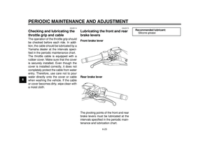
EAU44910
Front brake lever The front brake lever is located at the
right handlebar grip. To apply the front
brake, pull this lever toward the handle-
bar grip.
The front brake lever is equipped with a
position adjusting dial. To adjust the
distance between the front brake lever
and the handlebar grip, turn the adjust-
ing dial while holding the front brake le-
ver pushed away from the handlebar
grip. Make sure that the appropriate
setting on the adjusting dial is aligned1. Front brake lever
2. Brake lever position adjusting dial
3. “ ” mark
4. Distance between brake lever and handle-
bar grip
1
4
2
3
59C-9-E0.book 13 ページ 2011年9月11日 日曜日 午前9時27分
Page 29 of 96
INSTRUMENT AND CONTROL FUNCTIONS
3-14
234
5
6
7
8
9
with the “ ” mark on the front brake le-
ver.
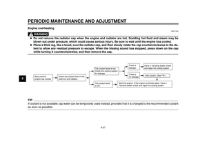
EAU44921
Rear brake lever The rear brake lever is located at the
left handlebar grip. To apply the rear
brake, pull this lever toward the handle-
bar grip.
The rear brake lever is equipped with a
position adjusting dial
. To adjust the
distance between the rear brake lever
and the handlebar grip, turn the adjust-
ing dial while holding the rear brake le-
ver pushed away from the handlebar
grip. Make sure that the appropriate
setting on the adjusting dial is aligned with the “ ” mark on the rear brake le-
ver.1. Rear brake lever
2. Brake lever position adjusting dial
3. “ ” mark
4. Distance between brake lever and handle-
bar grip
54321
32
1
4
59C-9-E0.book 14 ページ 2011年9月11日 日曜日 午前9時27分
Page 30 of 96

INSTRUMENT AND CONTROL FUNCTIONS
3-15
1
23
4
5
6
7
8
9
EAU12962
Rear brake lock lever This vehicle is equipped with a rear
brake lock lever to prevent the rear
wheel from moving while stopped at
traffic signals, railroad crossings, etc.
To lock the rear wheel
Push the rear brake lock lever to the left
until it snaps into place.
To unlock the rear wheel
Push the rear brake lock lever back to
the original position.TIP
Be sure to check that the rear
wheel does not move when therear brake lock lever is applied.
To provide secure locking of the
rear wheel, apply the rear brake le-
ver first before moving the rearbrake lock lever to the left.WARNING
EWA12361
Never move the rear brake lock lever
to the left while the vehicle is mov-
ing, otherwise loss of control or an
accident may result. Make sure that
the vehicle is stopped before mov-
ing the rear brake lock lever to theleft.
EAU13175
Fuel tank cap To remove the fuel tank cap
1. Open the lid by pulling the lever up.
2. Insert the key into the lock and turn it clockwise. The lock will be re-
leased and the fuel tank cap can
be removed.
1. Rear brake lock lever
1
1. Opening lever
2. Lid
1
2
59C-9-E0.book 15 ページ 2011年9月11日 日曜日 午前9時27分
Page 31 of 96

INSTRUMENT AND CONTROL FUNCTIONS
3-16
234
5
6
7
8
9
To install the fuel tank cap
1. Align the match marks, insert the fuel tank cap into the tank opening,
and then push down on the cap.
2. Turn the key counterclockwise to the original position, and then re- move it.
3. Close the lid.
WARNING
EWA11261
Make sure that the fuel tank cap is
properly installed and locked in
place before riding the scooter.Leaking fuel is a fire hazard.
EAU13221
Fuel Make sure there is sufficient gasoline in
the tank.
WARNING
EWA10881
Gasoline and gasoline vapors are
extremely flammable. To avoid fires
and explosions and to reduce the
risk of injury when refueling, followthese instructions.
1. Before refueling, turn off the en- gine and be sure that no one is sit-
ting on the vehicle. Never refuel
while smoking, or while in the vi-
cinity of sparks, open flames, or
other sources of ignition such as
the pilot lights of water heaters and
clothes dryers.
2. Do not overfill the fuel tank. When refueling, be sure to insert the
pump nozzle into the fuel tank filler
hole. Stop filling when the fuel
reaches the bottom of the filler
tube. Because fuel expands when
it heats up, heat from the engine or
the sun can cause fuel to spill out
of the fuel tank.
1. Fuel tank cap
1. Match mark
1
1
59C-9-E0.book 16 ページ 2011年9月11日 日曜日 午前9時27分
Page 32 of 96

INSTRUMENT AND CONTROL FUNCTIONS
3-17
1
23
4
5
6
7
8
93. Wipe up any spilled fuel immedi-
ately. NOTICE: Immediately wipe
off spilled fuel with a clean, dry,
soft cloth, since fuel may deteri-
orate painted surfaces or plastic
parts.
[ECA10071]
4. Be sure to securely close the fuel tank cap.
WARNING
EWA15151
Gasoline is poisonous and can
cause injury or death. Handle gaso-
line with care. Never siphon gaso-
line by mouth. If you should swallow
some gasoline or inhale a lot of gas-
oline vapor, or get some gasoline in your eyes, see your doctor immedi-
ately. If gasoline spills on your skin,
wash with soap and water. If gaso-
line spills on your clothing, change
your clothes.
EAU53010
NOTICE
ECA11400
Use only unleaded gasoline. The use
of leaded gasoline will cause severe
damage to internal engine parts,
such as the valves and piston rings,as well as to the exhaust system.
Your Yamaha engine has been de-
signed to use regular unleaded gaso-
line with a research octane number of
91 or higher. If knocking (or pinging) oc-
curs, use a gasoline of a different brand
or premium unleaded fuel. Use of un-
leaded fuel will extend spark plug lifeand reduce maintenance costs.
Gasohol
There are two types of gasohol: gaso-
hol containing ethanol and that contain-
ing methanol. Gasohol containing
ethanol can be used if the ethanol con-
tent does not exceed 10% (E10). Gas-
ohol containing methanol is not
recommended by Yamaha because it
can cause damage to the fuel system
or vehicle performance problems.
1. Fuel tank filler tube
2. Maximum fuel level2
1
Recommended fuel:
Regular unleaded gasoline or gaso-
hol (E10)
Fuel tank capacity: 15.0 L (3.96 US gal, 3.30 Imp.gal)
59C-9-E0.book 17 ページ 2011年9月11日 日曜日 午前9時27分


 This model can be equipped with an
optional anti-theft alarm by a Yamaha
dealer. Contact a Yamaha dealer for
mo")
