Page 17 of 98

1
2
3
4
5
6
7
8
9
10
INSTRUMENT AND CONTROL FUNCTIONS
3-3
To unlock the steering
1. Push
2. Turn
Push the key in, and then turn it to
“OFF” while still pushing it.
EWA10060
WARNING0
Never turn the key to “OFF” or
“LOCK” while the vehicle is moving,
otherwise the electrical systems
will be switched off, which may re-
sult in loss of control or an acci-
dent. Make sure that the vehicle is
stopped before turning the key to
“OFF” or “LOCK”.
EAU10941
F(Parking)
The steering is locked, and the tail-
light, license plate light and auxiliary
lights are on. The hazard lights and
turn signal lights can be turned on, but
all other electrical systems are off. The
key can be removed.
The steering must be locked before
the key can be turned to “F”.
ECA11020CAUTION:
Do not use the parking position for
an extended length of time, other-
wise the battery may discharge.
EAU11003
Indicator and warning lights
1. Immobilizer system indicator light “ ”
2. Neutral indicator light “N”
3. Turn signal indicator light “y”
4. High beam indicator light “1”
5. Engine trouble warning light “U”
6. Coolant temperature warning light “u”
7. Fuel level warning light “K”
EAU26873
Immobilizer system indicator
light “ ”
The electrical circuit of the indicator
light can be checked by turning the
key to “ON”.
If the indicator light does not come on
for a few seconds, then go off, have a
Yamaha dealer check the electrical
circuit.
Page 18 of 98

INSTRUMENT AND CONTROL FUNCTIONS
3-4
1
2
3
4
5
6
7
8
9
10
When the key is turned to “OFF” and
30 seconds have passed, the indicator
light will start flashing indicating the
immobilizer system is enabled. After
24 hours have passed, the indicator
light will stop flashing, however the im-
mobilizer system is still enabled.
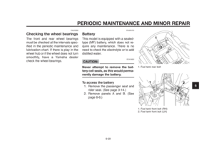
This model is also equipped with a
self-diagnosis device for the immobi-
lizer system. (See page 3-7 for an ex-
planation of the self-diagnosis device.)
EAU11060
Neutral indicator light “N”
This indicator light comes on when the
transmission is in the neutral position.
EAU11020
Turn signal indicator light “y”
This indicator light flashes when the
turn signal switch is pushed to the left
or right.
EAU11080
High beam indicator light “1”
This indicator light comes on when the
high beam of the headlight is switched
on.
EWA10060
WARNING0
Never turn the key to “OFF” or
“LOCK” while the vehicle is moving,
otherwise the electrical systems
will be switched off, which may re-
sult in loss of control or an acci-
dent. Make sure that the vehicle is
stopped before turning the key to
“OFF” or “LOCK”.
EAU11530
Engine trouble warning light “U”
This warning light comes on or flashes
when an electrical circuit monitoring
the engine is defective. When this oc-
curs, have a Yamaha dealer check the
self-diagnosis system. (See page 3-7
for an explanation of the self-diagno-
sis device.)
The electrical circuit of the warning
light can be checked by turning the
key to “ON”. If the warning light does
not come on for a few seconds, then
go off, have a Yamaha dealer check
the electrical circuit.
EAU11440
Coolant temperature warning
light “u”
This warning light comes on when the
engine overheats. When this occurs,
stop the engine immediately and allow
the engine to cool.
The electrical circuit of the warning
light can be checked by turning the
key to “ON”.
If the warning light does not come on
for a few seconds, then go off, have a
Yamaha dealer check the electrical
circuit.
ECA10020
CAUTION:
Do not operate the engine if it is
overheated.
EAU11361
Fuel level warning light “K”
This warning light comes on when the
fuel level drops below approximately
4.25 L (1.12 US gal) (0.93 Imp.gal).
When this occurs, refuel as soon as
possible.
Page 19 of 98

1
2
3
4
5
6
7
8
9
10
INSTRUMENT AND CONTROL FUNCTIONS
3-5
The electrical circuit of the warning
light can be checked by turning the
key to “ON”.
If the warning light does not come on
for a few seconds, and then go off,
have a Yamaha dealer check the elec-
trical circuit.
NOTE:
This model is also equipped with a
self-diagnosis device for the fuel level
detection circuit. If the fuel level detec-
tion circuit is defective, the following
cycle will be repeated until the mal-
function is corrected: The fuel level
warning light will flash eight times, and
then go off for 3.0 seconds. If this oc-
curs, have a Yamaha dealer check the
vehicle.
EAUB1392
Multi-function meter unit
1. Speedometer
2. Tachometer
3. Clock
4. Odometer/Tripmeters/Fuel reserve tripmeter
5. “SELECT” button
6. “RESET” button
EWA12421
WARNING0
Be sure to stop the vehicle before
making any setting changes to the
multi-function meter unit.
The multi-function meter unit is equip-
ped with the following:
●a speedometer (which shows the
riding speed)
●a tachometer (which shows en-
gine speed)
●an odometer (which shows the to-
tal distance traveled)
●two tripmeters (which show the
distance traveled since they were
last set to zero)
●a fuel reserve tripmeter (which
shows the distance traveled since
the fuel level warning light came on)
●a clock
●a self-diagnosis device
●an indicator lights brightness con-
trol mode
To switch the speedometer and
odometer/tripmeter displays between
kilometers and miles, push the “SE-
LECT” and “RESET” buttons together
and turn the key to “ON”. When the
digits start flashing on the display,
push the “SELECT” button to choose
kilometers or miles.
NOTE:
Be sure to turn the key to “ON” before
using the “SELECT” and “RESET”
buttons.
Page 20 of 98

INSTRUMENT AND CONTROL FUNCTIONS
3-6
1
2
3
4
5
6
7
8
9
10
Tachometer
1. Tachometer
2. Red zone
The electric tachometer allows the rid-
er to monitor the engine speed and
keep it within the ideal power range.
ECA10031CAUTION:
Do not operate the engine in the
tachometer red zone.
Red zone: 7,500 r/min and above.
Odometer, tripmeter modes
1. “SELECT” button
2. “RESET” button
Pushing the “SELECT” button switch-
es the display between the odometer
mode “ODO” and the tripmeter modes
“TRIP 1” and “TRIP 2” in the following
order:
ODO
6TRIP 1 6TRIP 2 6ODO
If the fuel level warning light comes on
(see page 3-4), the odometer display
will automatically change to the fuel
reserve tripmeter mode “F-TRIP” and
start counting the distance traveled
from that point. In that case, push the
“SELECT” button to switch the display
between the various tripmeter,
odometer modes in the following or-
der:
F-TRIP
6ODO6TRIP 1 6TRIP 2
6F-TRIP
To reset a tripmeter, select it by push-
ing the “SELECT” button, and then
push the “RESET” button for at least
four seconds. If you do not reset the
fuel reserve tripmeter manually, it will
reset itself automatically and the dis-
play will return to the prior mode after
refueling and traveling 5 km (3 mi).
Page 21 of 98

1
2
3
4
5
6
7
8
9
10
INSTRUMENT AND CONTROL FUNCTIONS
3-7
Clock mode
1. Clock
2. “SELECT” button
3. “RESET” button
Turn the key to “ON”.
T
o set the clock
1. Push the “SELECT” button for at
least two seconds.
2. When the hour digits start flash-
ing, push the “RESET” button to
set the hours.
3. Push the “SELECT” button, and
the minute digits will start flash-
ing.
4. Push the “RESET” button to set
the minutes.
5. Push the “SELECT” button, and
then release it to start the clock.
Self-diagnosis devices
1. Engine trouble warning light “U”
2. Immobilizer system indicator light “ ”
This model is equipped with a self-diag-
nosis device for various electrical cir-
cuits. If any of those circuits are defec-
tive, the engine trouble warning light
will start flashing. If this occurs, have a
Yamaha dealer check the vehicle.
This model is also equipped with a
self-diagnosis device for the immobi-
lizer system.
Turn the key to "ON". If any of the im-
mobilizer system circuits are defec-
tive, the immobilizer system indicator
light will flash, and it will indicate an er-
ror code.
If this occurs, have a Yamaha dealer
check the vehicle. However, if the indi-
cator light slowly flashes five times,
and then quickly flashes two times re-
peatedly, this error could be caused by
signal interference. If this occurs, try
the following.
1. Use the code re-registering key to
start the engine.
NOTE:
Make sure there are no other immobi-
lizer keys close to the main switch,
and do not keep more than one immo-
bilizer key on the same key ring! Im-
mobilizer system keys may cause sig-
nal interference, which may prevent
the engine from starting.
2. If the engine starts, turn it off and
try starting the engine with the
standard keys.
3. If one or both of the standard keys
do not start the engine, take the
vehicle, the code re-registering
key and both standard keys to a
Yamaha dealer and have the
standard keys re-registered.
Page 22 of 98
INSTRUMENT AND CONTROL FUNCTIONS
3-8
1
2
3
4
5
6
7
8
9
10
If the immobilizer system indicator
light flashes any error codes, have a
Yamaha dealer check the vehicle.
ECA11590CAUTION:
If the display indicates an error
code, the vehicle should be
checked as soon as possible in or-
der to avoid engine damage.Indicator lights brightness
control mode
●Indicator lights brightness:
This function allows you to adjust
the brightness of the indicator
lights to suit the outside lighting
conditions.
T
o adjust the brightness of the
indicator lights
1. Turn the key to “ON”.
2. Push the “SELECT” button to se-
lect ODO meter mode, and then
push the “RESET” button for at
least five seconds.
3. Release the “RESET” button, and
then select the desired lighting
brightness level by pushing the
“RESET” button.
EAU12331
Anti-theft alarm (optional)
This motorcycle can be equipped with
an optional anti-theft alarm by a Yama-
ha dealer. Contact a Yamaha dealer
for more information.
Page 23 of 98

EAU12343
Handlebar switches
Left
1. Pass switch “ ”
2. Dimmer switch “ / ”
3. Horn switch “ ”
4. Turn signal switch “ ”
5. Hazard switch “ ”
Right
1. Engine stop switch “ / ”
2. Start switch “ ”
EAU12350
Pass switch “ ”
Press this switch to flash the head-
light.
EAU12400
Dimmer switch “ / ”
Set this switch to “ ” for the high
beam and to “ ” for the low beam.
EAU12500
Horn switch “ ”
Press this switch to sound the horn.
EAU12460
Turn signal switch “ ”
To signal a right-hand turn, push this
switch to “ ”. To signal a left-hand
turn, push this switch to “ ”. When
released, the switch returns to the
center position. To cancel the turn sig-
nal lights, push the switch in after it
has returned to the center position.
EAU12660
Engine stop switch “/ ”
Set this switch to “ ” before starting
the engine. Set this switch to “ ” to
stop the engine in case of an emer-
gency, such as when the motorcycle
overturns or when the throttle cable is
stuck.
EAU12710
Start switch “ ”
Push this switch to crank the engine
with the starter.
ECA10050CAUTION:
See page 5-1 for starting instruc-
tions prior to starting the engine.
INSTRUMENT AND CONTROL FUNCTIONS
3-9
3
Page 24 of 98

INSTRUMENT AND CONTROL FUNCTIONS
3-10
1
2
3
4
5
6
7
8
9
10
EAU12733
Hazard switch “r”
With the key in the “ON” or Fposition,
use this switch to turn on the hazard
lights (simultaneous flashing of all turn
signal lights).
The hazard lights are used in case of
an emergency or to warn other drivers
when your vehicle is stopped where it
might be a traffic hazard.
ECA10061CAUTION:
Do not use the hazard lights for an
extended length of time with the
engine not running, otherwise the
battery may discharge.
EAU12820
Clutch lever
1. Clutch lever
The clutch lever is located at the left
handlebar grip. To disengage the
clutch, pull the lever toward the han-
dlebar grip. To engage the clutch, re-
lease the lever. The lever should be
pulled rapidly and released slowly for
smooth clutch operation.
The clutch lever is equipped with a
clutch switch, which is part of the igni-
tion circuit cut-off system. (See page
3-19).
EAU12870
Shift pedal
1. Shift pedal
The shift pedal is located on the left
side of the engine and is used in com-
bination with the clutch lever when
shifting the gears of the 5-speed con-
stant-mesh transmission equipped on
this motorcycle.