Page 185 of 225

Handling wheels and tyres
Fig. 149
Changing wheels around
First read and observe the introductory information and safety warn-
ings on page 181.
Changing wheels around
If significantly greater wear is present on the front tyres, we recommend chang-
ing the front wheels around with the rear wheels as shown in the dia-
gram » Fig. 149. You will then obtain approximately the same life for all the tyres.
We recommend that you change the wheels around every 10
000 km in order to
achieve even wear on all wheels and to obtain optimal tyre life.
Storing tyres
Mark wheels before removing them so that their previous direction of running can
be maintained when mounted them again.
Always store wheels or tyres which been removed in a cool, dry and, where possi-
ble, dark place. Tyres which are not fixed to a wheel trim should be stored up-
right. ÐNew wheels and tyres
First read and observe the introductory information and safety warn-
ings on page 181.
Only fit tyres of the same type, size (rolling circumference) and the same tread
pattern on one axle on all 4
wheels.
The tyre/wheel combinations which are approved for your vehicle are indicated in
your vehicle documents.
ä
ä Proper knowledge of the tyre data makes it easier for you to select the correct
type of tyre. Tyres, for example, have the following inscription on their walls.
225/50R
17 91 T
What this means is:
225 Tyre width in mm
50 Height/width ratio in %
R Code letter for the type of tyre - Radial
17 Diameter of wheel in inches
91 Load index
T Speed symbol The following speed restrictions apply to tyres.
Speed symbol Permissible maximum speed
S 180 km/h
T 190 km/h
U 200 km/h
H 210 km/h
V 240 km/h
W 270 km/h
Y 300 km/h The date of manufacture
is also stated on the tyre wall (possibly only on the in-
side of wheel ): e.g.
DOT ... 20
12...
means, for example, that the tyre was manufactured in the 20th week of 2012.
The following must be observed if only one temporary spare wheel is availa-
ble » page 184. Ð
183
Wheels and Tyres
Page 186 of 225

Unidirectional tyres
First read and observe the introductory information and safety warn-
ings on page 181.
The direction of rotation of the tyres is marked by arrows on the wall of the tyre
.
The so specified running direction must absolutely be complied with. Only then
are the tyres able to provide the optimal properties in terms of grip, low noise,
wear-and-tear and aquaplaning.
If, in the event of a puncture, it is necessary to fit a spare wheel with a tyre with-
out a dedicated running direction or the opposite running direction, drive carefully
as the optimum characteristics of the tyre are no longer applicable in this situa-
tion. ÐSpare wheel
Fig. 150
Boot: Spare wheel
First read and observe the introductory information and safety warn-
ings on page 181.
The spare wheel is located in a well under the floor covering in the boot and is
fixed in place with a special bolt
» Fig. 150.
Before removing the spare wheel, the box containing the vehicle tool kit must be
removed.
It is important to check the inflation pressure in the spare wheel (preferably every
time the tyre air pressure is checked - see sticker on the fuel filler flap »
page 182)
to ensure it is always ready to use.
ä
ä
If the dimensions or design of the spare wheel differ from the tyres fitted to the
vehicle (e.g. winter tyres or low-profile tyres), it must only be used briefly in the
event of a puncture and if an appropriately cautious style of driving is adop-
ted » .
Replace it with a wheel having the appropriate mode and dimensions as soon as
possible
Temporary spare wheel
A warning label is displayed on the wheel rim of the spare wheel to indicate that
your vehicle is equipped with a temporary spare wheel.
Please observe the following when driving with a temporary spare wheel.
› The warning label must not be covered after installing the wheel.
› Do not drive faster than 80
km/h with the temporary spare wheel and pay par-
ticular attention while driving. Avoid accelerating at full throttle, sharp braking
and fast cornering.
› The inflation pressure for this spare wheel is identical to the maximum inflation
pressure of the standard tyres.
› Only use this temporary spare wheel to reach the nearest ŠKODA specialist ga-
rage as it is not intended for continuous use. WARNING
■ Never use the temporary spare wheel if it is damaged.
■ If the dimensions or design of the temporary spare wheel differ from the fit-
ted tyres, never drive faster than 80
km/h (or 50 mph). Avoid accelerating at
full throttle, sharp braking and fast cornering. CAUTION
Observe the instructions on the sticker on the temporary spare wheel. Note
The tyre pressure should be at the highest pressure specified for your vehicle at
all times. Ð
184 General Maintenance
Page 187 of 225

Full wheel trim
First read and observe the introductory information and safety warn-
ings on page 181.
Pulling off
›
Hook the clamp found in the vehicle tool kit into the reinforced edge of the
wheel trim.
› Push the wheel wrench through the clamp, support on the tyre and pull off the
wheel trim.
Install
› First press the full wheel trim onto the wheel rim at the valve opening provided.
Then press the full wheel trim into the wheel rim until its entire circumference
locks correctly in place. CAUTION
■ Use the pressure of your hand, do not knock the full wheel trim! Heavy knocks
mainly on the points where the full wheel trim has not been inserted into the
wheel, can result in damage to the guide and centring elements of the full wheel
trim.
■ First of all check that the theft-deterrent wheel bolt is located in the hole near
the valve before fitting the full wheel trim onto a steel wheel which is attached
with a theft-deterrent wheel bolt » page 194, Securing wheels against theft .
■ If wheel trims are retrofitted it must be ensured that an adequate flow of air is
assured to cool the brake system. ÐWheel bolts
Fig. 151
Remove the cap
ä
First read and observe the introductory information and safety warn-
ings on page 181.
Pulling off
›
Push the plastic clip sufficiently far onto the cap until the inner catches of the
clip are positioned at the collar of the cap and detach the cap » Fig. 151.
Install
› Push the caps onto the wheel bolts up to the stop.
The wheel bolt caps are housed in a plastic box in the spare wheel or in the stor-
age space for the spare wheel. Ð Wheel trim caps
Fig. 152
Pull off the wheel trim cap on
light alloy wheels
First read and observe the introductory information and safety warn-
ings on page 181.
Pulling off
›
Carefully remove the wheel trim cap using the wire clamp from the vehicle tool
kit » Fig. 152. Ð
ä
ä
185
Wheels and Tyres
Page 188 of 225

Tyre control display
Fig. 153
Button for setting the tyre infla-
tion pressure control value
First read and observe the introductory information and safety warn-
ings on page 181.
The tyre control display compares the speed and thus the rolling circumference of
the individual wheels with the help of the ABS sensors. If the rolling circumfer-
ence of a wheel is changed, the indicator light
in the instrument clus-
ter » page 24, Tyre control display and an audible signal sounds.
The rolling circumference of the tyre can change if: › the tyre inflation pressure is too low;
› the structure of the tyre is damaged;
› the vehicle is loaded on one side;
› the wheels of an axle are loaded heavily (e.g. when towing a trailer or when
driving uphill or downhill);
› snow chains are mounted;
› the temporary spare wheel is mounted;
› one wheel per axle was changed.
Basic setting of the system
After changing the tyre inflation pressure, after changing one or several wheels,
the position of a wheel on the vehicle (e.g. exchanging the wheels between the
axles) or when the indicator light lights up while driving, a basic setting of the
system must be carried out as follows:
› Inflate all of the tyres to the specified inflation pressure
» page 182, Service life
of tyres.
› Switch on the ignition.
ä
›
Press and hold the button
» Fig. 153 for longer than 2
seconds. While
pressing the button, the indicator light illuminates. At the same time the sys-
tem memory is erased and the new calibration is started, which is confirmed
with an audible signal and then the indicator light goes out.
› If the indicator light
does not go out after the basic setting, this indicates a
system fault. Seek help from a ŠKODA specialist garage.
The indicator light is lit
If the tyre inflation pressure of at least one wheel is insufficiently inflated in com-
parison to the stored basic value, the indicator light » lights up.
The indicator light flashes
If the indicator light flashes, there is a system fault. Seek help from a
ŠKODA spe-
cialist garage to correct the fault. WARNING
■ When the indicator light illuminates, immediately reduce the speed and
avoid sudden steering and brake manoeuvres. Stop the vehicle as soon as
possible and inspect the tyres and their inflation pressure.
■ Under certain circumstances (e.g. sporty style of driving, wintry or unpaved
roads) the indicator light can be delayed or does not light up at all.
■ The tyre control display does not absolve the driver of the responsibility to
ensure the correct tyre inflation pressure. For this reason, the tyre inflation
pressure must be checked regularly. Note
■ The tyre control display does therefore not replace the regular tyre inflation
pressure control, as the system cannot detect an even loss of pressure. ■ The tyre control display cannot provide a warning in the event of very rapid tyre
inflation pressure loss, e.g. in the case of sudden tyre damage. In this case care-
fully bring the vehicle to a standstill without sudden steering movements or
sharp braking.
■ To ensure a proper functioning of the tyre control display, it is necessary to re-
peat the basic setting every 10 000 km or once a year. Ð
186 General Maintenance
Page 189 of 225

Wheel bolts
First read and observe the introductory information and safety warn-
ings on page 181.
Wheels and
wheel bolts are matched to each other in terms of design. Each time
you fit other wheels, e.g. light alloy wheels or wheels with winter tyres, you must
therefore also use the matching wheel bolts of the correct length and shape of
spherical cap. This is essential to ensure that the wheels are tightly fitted and
that the brake system operates properly. ÐWinter tyres
First read and observe the introductory information and safety warn-
ings on page 181.
The handling of your vehicle will be significantly improved when driving on wintry
roads if you fit winter tyres. Summer tyres do not offer the same grip on ice, snow
and at temperatures below 7 °C because of their construction (width, rubber
blend, tread pattern). This particularly applies to vehicles which are equipped with
low-profile tyres
or high-speed tyres (code index H or V on wall of tyre).
To achieve the best possible handling properties, winter tyres must be fitted on
all 4 wheels, the minimum tread depth must be 4
mm and tyres must be no older
than 4 years.
Winter tyres of a lower speed category can be used provided that the permissible
maximum speed of these tyres is not exceeded even if the possible maximum
speed of the vehicle is higher. For the sake of the environment
Fit the summer tyres on again in good time as they provide better handling prop-
erties, a shorter braking distance, less tyre noise, and reduced tyre wear on roads
which are free of snow and ice as well as at temperatures above 7
°C. The fuel
consumption is also lower. ÐSnow chains
First read and observe the introductory information and safety warn-
ings on page 181.ä
ä
ä
Snow chains must only be mounted on the front wheels.
When driving on wintry roads, snow chains improve not only traction, but also the
braking performance.
For technical reasons, it is only permissible to fit snow chains with the following
wheel/tyre combinations.
Valid for vehicles with front-wheel drive
For technical reasons, it is only permissible to fit snow chains with the following
wheel/tyre combinations.
Wheel size Depth (D)Tyre size
6J x 16 50 mm 205/55
7J x 16 45 mm 205/55
6J x 17 45 mm 205/50 Valid for vehicles with four-wheel drive
Snow chains can be used on the front wheels as on vehicles with front-wheel
drive » page 187, Valid for vehicles with front-wheel drive
.
In order to increase the traction (start-up properties), the use of snow chains is
also technically permissible on the rear axle (this means on the front and rear axle
at the same time) for the following wheel/tyre combinations.
Wheel size Depth (D)Tyre size
6J x 16 50 mm 205/55
7J x 16 45 mm 205/55
6J x 17 45 mm 205/50 The use of snow chains is only technically permissible on the rear axle for the fol-
lowing standard wheel/tyre combinations.
Wheel size Depth (D)Tyre size
7J x 16 45 mm 215/60
7J x 17 45 mm 225/50 When fitting snow chains on the front and rear axle at the same time, the maxi-
mum speed is limited to
50 km/h.
Only fit snow chains with links and locks not larger than 12 mm.
Remove the full wheel trims before installing the snow chains.
Observe the national legal regulations relating to the use of snow chains and the
maximum vehicle speed with snow chains. £
187
Wheels and Tyres
Page 190 of 225
CAUTION
The chains must be removed when driving on roads which are free of snow. They
adversely affect the handling of your vehicle, damage the tyres and are rapidly
destroyed. Ð188
General Maintenance
Page 191 of 225

Accessories, changes and replacement of
parts Introductory information
If you want to retrofit the vehicle with accessories, if a vehicle part is to be re-
placed with a new one, or when needing to make technical changes, the follow-
ing instructions must be observed.
› Always seek advice from a
ŠKODA Service Partner before purchasing any acces-
sories or parts and before making any technical changes » .
› The guidelines and instructions issued by
ŠKODA must be observed when mak-
ing technical changes.
Adhering to the prescribed procedures will prevent any kind of damage to the ve-
hicle, and its travelling and operating safety will be maintained. The vehicle also
complies with German road transport regulations (StVZO). More information is
available from a ŠKODA Service Partner who can also perform the necessary work
correctly.
Vehicles with special built-on types
Technical documents regarding changes carried out on the vehicle must be kept
by the vehicle user, in order to hand over later to the old car user. This ensures
the recycling in accordance with environmental regulations.
Interference on the electronic components and their software can lead to opera-
tional faults. This interference can also impair not directly affected systems be-
cause of the networking of the electronic components. In other words, the vehi-
cle's roadworthiness may be put at risk and increased wear on parts may arise.
Any damage caused by technical changes made without consent by ŠKODA is ex-
cluded from the warranty – see the warranty certificate. WARNING
■ Work or modifications on your vehicle, which have been carried out unpro-
fessionally, can cause operational faults - risk of accident!
■ We advise you, in your own interest, to only use ŠKODA Original Accessories
and ŠKODA Original Parts which have been expressly approved for use on
your vehicle. Reliability, safety and suitability have been established for
ŠKODA Original Accessories and
ŠKODA Original Parts.
■ Although we constantly monitor the market, we are not able to assess or
warrant the parts even though in some instances such parts may have a type
approval or may have been approved by a nationally recognised testing labo-
ratory. Note
ŠKODA Original Accessories and ŠKODA Original Parts can be purchased from
ŠKODA
Service Partners who will also professionally undertake the assembly of
the purchased parts. Ð Changes and impairments of the airbag system
Repairs and technical modifications must comply with
ŠKODA guidelines.
We recommend that any modifications and repairs to the front bumper, doors,
front seats, headliner or bodywork be carried out by a ŠKODA Service Partner.
These vehicle parts may include system components for the airbag system. WARNING
■ Airbag modules can not be repaired, but must be replaced.
■ Never install any airbag parts into the vehicle that have been removed from
old cars or have been recycled. ■ A modification to the suspension of the vehicle including the use of non-ap-
proved rim-tyre combinations can alter the functioning of the airbag and in-
crease the risk of serious or fatal injuries in an accident.
■ Parts of the airbag system may be damaged when working on the airbag
system or removing and installing system parts due to other repairs. This may
mean that the airbags will not deploy properly or not at all in the event of an
accident. Ð
189
Accessories, changes and replacement of parts
Page 192 of 225

Do-it-yourself
Do-it-yourself
First-aid kit and warning triangle
Fig. 154
Placing of the warning triangle/placing of the first-aid box
The warning triangle can be attached to the rear wall trim panel with rubber
straps » Fig. 154 - .
The warning triangle, which is included in the equipment with the spare wheel,
can be stowed in a removable box on the right next to the spare wheel » page 68.
The first-aid box is attached by a strap to the right-hand side of the
boot »
Fig. 154 - . WARNING
The first-aid kit and warning triangle must always be secured safely so that
they do not come loose when making an emergency braking or in a vehicle
collision which could cause injuries to occupants. Note
■ Pay attention to the expiration date of the first-aid kit.
■ We recommend using a first-aid box from ŠKODA Original Accessories available
from a
ŠKODA Service Partner. Ð Fire extinguisher
The fire extinguisher is attached with straps in a holder under the driver seat.
Please read carefully the instructions which are attached to the fire extinguish-
er.
The fire extinguisher must be checked by an authorised person on an annual ba-
sis (the national legal provisions must be observed). WARNING
The fire extinguisher must always be secured safely so that they do not come
loose when making an emergency braking or in a vehicle collision which could
cause injuries to occupants. Note
■ The fire extinguisher must comply with the relevant applicable national legal re-
quirements. ■ Pay attention to the expiration date of the fire extinguisher. If the fire extin-
guisher is used after the expiration date, its proper function is no longer assured.
■ The fire extinguisher is part of the scope of delivery in certain countries only. Ð Vehicle tool kit
Fig. 155
Boot: Example for placing the vehicle tool kit £
190 Do-it-yourself
 1
1 2
2 3
3 4
4 5
5 6
6 7
7 8
8 9
9 10
10 11
11 12
12 13
13 14
14 15
15 16
16 17
17 18
18 19
19 20
20 21
21 22
22 23
23 24
24 25
25 26
26 27
27 28
28 29
29 30
30 31
31 32
32 33
33 34
34 35
35 36
36 37
37 38
38 39
39 40
40 41
41 42
42 43
43 44
44 45
45 46
46 47
47 48
48 49
49 50
50 51
51 52
52 53
53 54
54 55
55 56
56 57
57 58
58 59
59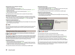 60
60 61
61 62
62 63
63 64
64 65
65 66
66 67
67 68
68 69
69 70
70 71
71 72
72 73
73 74
74 75
75 76
76 77
77 78
78 79
79 80
80 81
81 82
82 83
83 84
84 85
85 86
86 87
87 88
88 89
89 90
90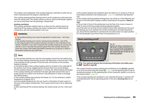 91
91 92
92 93
93 94
94 95
95 96
96 97
97 98
98 99
99 100
100 101
101 102
102 103
103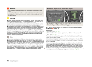 104
104 105
105 106
106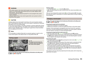 107
107 108
108 109
109 110
110 111
111 112
112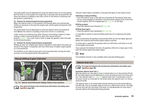 113
113 114
114 115
115 116
116 117
117 118
118 119
119 120
120 121
121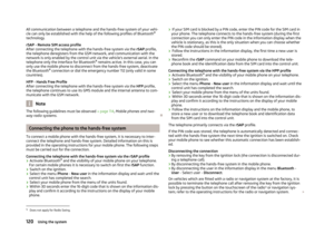 122
122 123
123 124
124 125
125 126
126 127
127 128
128 129
129 130
130 131
131 132
132 133
133 134
134 135
135 136
136 137
137 138
138 139
139 140
140 141
141 142
142 143
143 144
144 145
145 146
146 147
147 148
148 149
149 150
150 151
151 152
152 153
153 154
154 155
155 156
156 157
157 158
158 159
159 160
160 161
161 162
162 163
163 164
164 165
165 166
166 167
167 168
168 169
169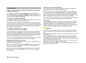 170
170 171
171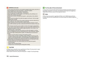 172
172 173
173 174
174 175
175 176
176 177
177 178
178 179
179 180
180 181
181 182
182 183
183 184
184 185
185 186
186 187
187 188
188 189
189 190
190 191
191 192
192 193
193 194
194 195
195 196
196 197
197 198
198 199
199 200
200 201
201 202
202 203
203 204
204 205
205 206
206 207
207 208
208 209
209 210
210 211
211 212
212 213
213 214
214 215
215 216
216 217
217 218
218 219
219 220
220 221
221 222
222 223
223 224
224