Page 161 of 180
 Fig. 125
Vehicle battery: Co")
Note
Fuses 1 - 7 are replaced by a specialist ŠKODA garage. ÐReplacing the fuses in the engine compartment
Fig. 124
Vehicle battery: Cover for the fuse box (variant 1) Fig. 125
Vehicle battery: Cover for the fuse box (variant 2)
First read and observe the introductory information and safety warn-
ings on page 156.
›
Press together the interlocks of the cover simultaneously in the direction of the
arrow 1
» Fig. 124.
› Push the cover in the direction of the arrow 2
.
› Use a flat screwdriver to release the fixtures in the openings 3
.
› Lift the cover upwards in the direction of the arrow 4
.
Ð
ä Bulbs
ä
Introduction
This chapter contains information on the following subjects:
Headlights 160
Changing the bulb for the low beam 160
Changing the bulb for main beam, separate daytime running lights, and
parking light 161
Changing the bulb for the front turn signal light 161
Changing light bulbs for fog lights 162
Changing the bulb for the licence plate light 162
Tail lamp assembly 163
Replacing the bulbs in the tail lamp assembly 163
Some manual skills are required to change a bulb. For this reason, if uncertain, we
recommend that bulbs are replaced by a ŠKODA specialist garage or other expert
help is sought.
› Switch off the ignition and all of the lights before replacing a bulb.
› Faulty bulbs must only be replaced with the same type of bulbs. The designa-
tion is located on the light socket or the glass bulb.
› A stowage compartment for replacement bulbs is located in a plastic box in the
spare wheel or underneath the floor covering in the boot. WARNING
■ Accidents can be caused if the road in front of the vehicle is not sufficiently
illuminated and the vehicle cannot or can only be seen with difficulty by other
road users.
■ Always read and observe the warnings before completing any work in the
engine compartment »
page 126, Engine compartment .
■ Bulbs H7 and H15 are pressurised and may burst when changing the bulb -
risk of injury! We therefore recommended wearing gloves and safety glasses
when changing a bulb. £
159
Fuses and light bulbs
Page 162 of 180
. Use a clean cloth, nap-
kin, or similar. ■ When remov")
CAUTION
■ Do not take hold of the glass bulb with naked fingers (even the smallest
amount of dirt reduces the working life of the light bulb). Use a clean cloth, nap-
kin, or similar. ■ When removing and installing the tail light make sure that the paintwork of the
vehicle and the tail light are not damaged. Note
■ This Owner's Manual only describes the replacement of bulbs where it is possi-
ble to replace the bulbs on your own without any complications arising. Other
light bulbs should be changed by a
ŠKODA specialist garage.
■ We recommend that a box of replacement bulbs be always carried in the vehi-
cle. Replacement bulbs can be purchased from
ŠKODAOriginal Accessories.
■ We recommend that the headlight settings are checked by a ŠKODA specialist
garage after replacing a bulb in the main or low beam.
■ LED diodes should be changed by a specialist ŠKODA garage. ÐHeadlights
Fig. 126
Bulb arrangement: Halogen
headlight
First read and observe the introductory information and safety warn-
ings on page 159.
Bulb arrangement in the Halogen headlamp
Low beam
Main beam, separate daytime running lights, and parking light
Turn signal light (at the front) Ð
ä A
B
C Changing the bulb for the low beam
Fig. 127
Changing the bulb for the low
beam
First read and observe the introductory information and safety warn-
ings on page 159.
›
Remove the rubber cover A
» Fig. 126 on page 160
» page 160.
› Remove the connector with the bulb by pulling it back in the direction of the
arrow with loosening movements »
Fig. 127.
› Remove the connector.
› Insert a new light bulb in such a way that the fixing lugs of the bulb fit in the
recesses of the reflector.
› Fit the connector.
› Insert the rubber cover. Ð
ä
160 Do-it-yourself
Page 163 of 180

Changing the bulb for main beam, separate daytime running
lights, and parking light
Fig. 128
Changing the bulb for main beam, separate daytime running lights,
and parking light
First read and observe the introductory information and safety warn-
ings on page 159.
Removing and replacing the bulb for main beam and separate daytime running
lights
›
Remove the rubber cover B
» Fig. 126 on page 160
» page 160.
› Turn the bulb holder A
» Fig. 128 anti-clockwise
up to the stop and remove.
› Replace the bulb, insert the bulb holder with the new bulb and turn in a
clock-
wise direction to the stop.
› Insert the rubber cover.
Removing and replacing the bulb for the parking light
› Remove the rubber cover B
» Fig. 126 on page 160
» page 160.
› Remove the socket C
» Fig. 128
together with the bulb with loosening move-
ments.
› Remove the faulty bulb from the bulb holder C
in the direction of the arrow.
› Insert a new bulb in the bulb holder up to the stop.
› Replace the bulb holder in the headlamp with the bulb.
› Insert the rubber cover. Ð
ä Changing the bulb for the front turn signal light
Fig. 129
Changing the bulb for the turn
signal light
First read and observe the introductory information and safety warn-
ings on page 159.
›
Turn the socket with the bulb
» Fig. 129 anti-clockwise up to the stop and re-
move.
› Replace the bulb, insert the socket with the new bulb and turn
clockwise up to
the stop. Ð
ä
161
Fuses and light bulbs
Page 164 of 180

Changing light bulbs for fog lights
Fig. 130
Front bumper: Protective grille/removing the fog light Fig. 131
Replacing the light bulb
First read and observe the introductory information and safety warn-
ings on page 159.
Removing the protective grille
›
Remove the protective grille by inserting the clamp for removing the wheel
trims at the location » Fig. 130 - indicated by the arrow » page 145, Vehicle
tool kit .
› Remove the protective grille in the direction of the arrow
» Fig. 130.
Changing light bulbs for fog lights
› Use the screwdriver from the tool kit to unscrew the fog lamp
» Fig. 130 -
.
› Remove the fog lamp in the direction of the arrow.
› Remove the connector.
› Turn the bulb holder A
» Fig. 131 in an anti-clockwise
direction up to the stop
and remove.
ä ›
Insert the bulb holder into the lamp and turn in a
clockwise direction as far as
the stop.
› Fit the connector.
› Replace the fog lamp by inserting it in the opposite direction of the ar-
row » Fig. 130 - and tighten.
› Insert the protective grille and carefully press it in. The protective grille must
engage firmly. Ð Changing the bulb for the licence plate light
Fig. 132
Remove the number plate light/replace the bulb
First read and observe the introductory information and safety warn-
ings on page 159.
›
Open the boot lid.
› Insert a flat screwdriver at the location indicated by the arrow
» Fig. 132 - ,
press it in lightly, and unlatch the springs.
› Remove the lamp.
› Pull the faulty bulb out of the holder in the direction of the arrow
» Fig. 132 - .
› Insert a new bulb into the holder.
› Replace the lamp and lightly press it until the spring latches. Ð
ä
162 Do-it-yourself
Page 165 of 180

Tail lamp assembly
Fig. 133
Removing the cover of the lamp/removing the lamp Fig. 134
Installing the lamp connector/lamp
First read and observe the introductory information and safety warn-
ings on page 159.
Removing the tail lamp assembly
›
Open the boot lid.
› Insert the clamp for removing the wheel trims
» page 145, Vehicle tool kit into
the hole indicated by the arrow » Fig. 133 - .
› Remove the cover in the direction of the arrow.
› Use the screwdriver from the tool kit
» Fig. 133 - to unscrew the lamp.
› Grip the tail lamp assembly and carefully remove it by pulling it back at an angle
with loosening movements.
› Pull the locking mechanism 1
» Fig. 134 on the connector in the direction of
the arrow.
› Press the locking mechanism 2
» Fig. 134 and remove the connector.
ä Installing the tail lamp assembly
› Insert the connector into the lamp and lock it securely.
› Carefully press the tail lamp assembly into the bodywork so that the bolts 2
» Fig. 135 on page 163 latch with the mounts in the body
» Fig. 134 - .
› Screw the tail lamp into place and install the cover. Ensure that the cover en-
gages firmly. Ð Replacing the bulbs in the tail lamp assembly
Fig. 135
Outer part of the lamp/inner part of the lamp
First read and observe the introductory information and safety warn-
ings on page 159.
Changing the bulb in the outer part of the lamp
›
Turn the bulb holder 1
» Fig. 135 anti-clockwise
remove it from the lamp hous-
ing.
› Replace the bulb, insert the holder with the bulb into the lamp housing and
turn in a clockwise direction to the stop.
Changing the bulb in the inner part of the lamp
› Unlock the bulb holder using the locking latches
» Fig. 135 - and remove the
holder from the tail lamp.
› Turn the bulb holder
anti-clockwise up to the stop and remove it from the lamp
housing » Fig. 135 - .
› Replace the bulb, insert the holder with the bulb into the lamp housing and
turn in a clockwise direction to the stop.
› Insert the bulb holder in the tail lamp assembly. All locking mechanisms must
audibly snap into place. Ð
ä
163
Fuses and light bulbs
Page 166 of 180

Technical data
Technical data
Introductory information
The details given in the vehicle's technical documentation always take prece-
dence over the details in the Owner's Manual. Please refer to the official vehicle
registration documents or consult a
ŠKODA Service Partner to determine which
engine your vehicle is equipped with.
The listed performance values were determined without performance-reducing
equipment, e.g. air conditioning system.
Vehicle identification number (VIN)
The vehicle identification number - VIN (vehicle body number) is stamped into the
engine compartment on the right hand suspension strut dome. This number is al-
so located on a sign on the lower left hand edge below the windscreen (together
with a VIN bar code).
Engine number
The engine number is stamped into the engine block. ÐData on the vehicle sticker and the type plate
Fig. 136
Vehicle data sticker/type plate Vehicle data sticker
The vehicle data sticker » Fig. 136 is located on the floor of the boot and is also
stated in the service schedule.
The vehicle data sticker contains the following data:
Vehicle identification number (VIN)
Vehicle type
Gearbox code/paint number/interior equipment/engine output/engine code
Partial vehicle description
Operating weight (in
kg)
Fuel consumption (in ltr./100 km) - intra-urban/extra-urban/combined
CO 2 emission levels - combined (in g/km)
Type plate
The type plate » Fig. 136 is located on the lower part of the column between the
front and rear doors on the driver's side.
The type plate lists the following weights:
Maximum permissible gross weight
Maximum permissible towed weight (towing vehicle and trailer)
Maximum permissible front axle load
Maximum permissible rear axle load
Operating weight
The specified operating weight is for orientation purposes only. This value repre-
sents the minimum operating weight without additional weight-increasing equip-
ment such as air conditioning system, spare wheel, or trailer hitch.
The operating weight also contains the weight of the driver (75 kg), the weight of
the operating fluids, the tool kit, and a fuel tank filled to 90 % capacity.
It is possible to calculate the approximate loading capacity from the difference
between the permissible total weight and the operating weight » .
The payload consists of the following components:
› Passengers
› All items of luggage and other loads
› Roof load including roof rack system
› Equipment not included in the operating weight
› Trailer drawbar load when towing a trailer (max. 50 kg).
£ 1
2
3
4
5
6
7
8
9
10
11
164
Technical data
Page 167 of 180

Measuring the fuel consumption and CO
2 emissions according to the ECE
standards and EU guidelines
The measurement of the intra-urban cycle begins with a cold start of the engine.
Afterwards urban driving is simulated.
In the extra-urban driving cycle, the vehicle is accelerated and decelerated in all
gears, corresponding to daily routine driving conditions. The driving speed varies
between 0 and 120 km/h.
The calculation of the combined fuel consumption considers a weighting of about
37
% for the intra-urban cycle and 63 % for the extra-urban cycle. WARNING
Do not exceed the specified maximum permissible weights - risk of accident
and damage. Note
■ If required, you can find out the precise weight of your vehicle by contacting a
ŠKODA
Service Partner.
■ Depending on the range of equipment, style of driving, traffic situation, weather
influences and vehicle condition, consumption values may deviate from the indi-
cated values. ÐDimensions
Dimensions (mm) Length 4483
Width 1706
Width including exterior mirror 1940
Height 1461/1488
a)
1474 b)
/1500 b)
a)
Clearance 136/143b)
Wheel base 2602
Track gauge front/rear 1457/1494
(1463/1500) c)a)
The value is valid for vehicles with the Amundsen+ navigation system.
b) The value corresponds to the status with the rough road package.
c) 1.2 ltr./55 kW and 1.2 ltr./63 kW TSI. Ð 165
Technical data
Page 168 of 180

Specifications and engine oil capacity
The engine has been factory-filled with a high-grade oil that can be use through-
out the year - except in extreme climate zones.
Various oils can be mixed together when refilling. However, this does not apply to
vehicles with flexible service intervals.
Engine oils are, of course, undergoing continuous further development. Thus the
information stated in this Owner's Manual is only correct at the time of publica-
tion.
ŠKODA Service Partners are informed about the latest changes by
ŠKODA. We
therefore recommend that the oil change is completed by a ŠKODA Service Part-
ner.
The specifications (VW standards) stated in the following can be indicated sepa-
rately or together with other specifications on the bottle.
The oil capacities include oil filter change. Check the oil level when filling; do not
over fill. The oil level must be between the markings » page 129.
Specifications and capacity (in l) for vehicles with flexible service intervals Petrol engines SpecificationFilling level
1.2 l/55 kW VW 503 00, VW 504 00 2.8
1.2 ltr./63 kW TSI VW 504 003.9
1.2 ltr./77 kW TSI VW 504 003.9
1.4 ltr./90 kW TSI VW 503 00, VW 504 00 3.6Diesel engine
SpecificationFilling level
1.6 ltr./77 kW TDI CR VW 507 004.3Specifications and capacity (in l) for vehicles with fixed service intervals
Petrol engines SpecificationFilling level
1.2 l/55 kW VW 501 01, VW 502 002.8
1.2 ltr./63 kW TSI VW 502 003.9
1.2 ltr./77 kW TSI VW 502 003.9
1.4 ltr./90 kW TSI VW 501 01, VW 502 003.6If the oils specified above are not available, oils according to ACEA
A2 or ACEA A3
can be used once for refilling. Diesel engine
SpecificationFilling level
1.6 ltr./77 kW TDI CR VW 507 004.3 If the oils specified above are not available, oils according to ACEA
B3 or ACEA B4
can be used once for refilling. CAUTION
Only the above-mentioned oils can be used on vehicles with flexible service inter-
vals. We recommend always refilling with oil of the same specification since this
will maintain the properties of the oil. In exceptional cases, a maximum of 0.5
l of
specification VW 502 00 (only for petrol engines) or specification VW 505 01 (only
for diesel engines) engine oil can be used to refill once. Other engine oils must
not be used - risk of engine damage! Note
■ Before a long drive we recommend that you purchase and carry with you engine
oil which complies with the specification for your vehicle. ■ We recommend that you use oils from ŠKODA Original Accessories. Ð166
Technical data
 1
1 2
2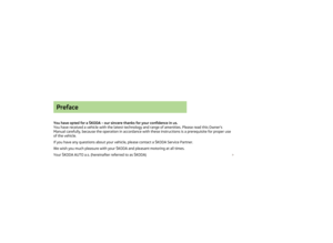 3
3 4
4 5
5 6
6 7
7 8
8 9
9 10
10 11
11 12
12 13
13 14
14 15
15 16
16 17
17 18
18 19
19 20
20 21
21 22
22 23
23 24
24 25
25 26
26 27
27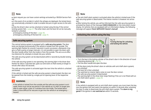 28
28 29
29 30
30 31
31 32
32 33
33 34
34 35
35 36
36 37
37 38
38 39
39 40
40 41
41 42
42 43
43 44
44 45
45 46
46 47
47 48
48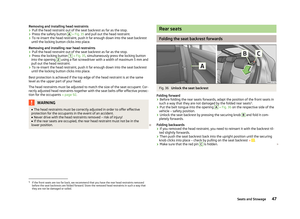 49
49 50
50 51
51 52
52 53
53 54
54 55
55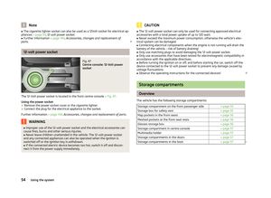 56
56 57
57 58
58 59
59 60
60 61
61 62
62 63
63 64
64 65
65 66
66 67
67 68
68 69
69 70
70 71
71 72
72 73
73 74
74 75
75 76
76 77
77 78
78 79
79 80
80 81
81 82
82 83
83 84
84 85
85 86
86 87
87 88
88 89
89 90
90 91
91 92
92 93
93 94
94 95
95 96
96 97
97 98
98 99
99 100
100 101
101 102
102 103
103 104
104 105
105 106
106 107
107 108
108 109
109 110
110 111
111 112
112 113
113 114
114 115
115 116
116 117
117 118
118 119
119 120
120 121
121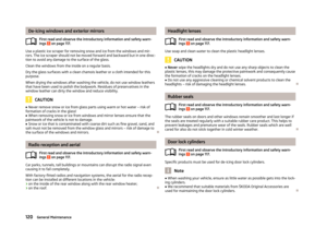 122
122 123
123 124
124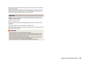 125
125 126
126 127
127 128
128 129
129 130
130 131
131 132
132 133
133 134
134 135
135 136
136 137
137 138
138 139
139 140
140 141
141 142
142 143
143 144
144 145
145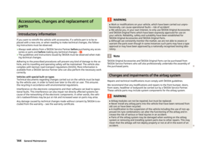 146
146 147
147 148
148 149
149 150
150 151
151 152
152 153
153 154
154 155
155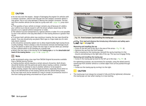 156
156 157
157 158
158 159
159 160
160 161
161 162
162 163
163 164
164 165
165 166
166 167
167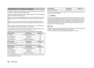 168
168 169
169 170
170 171
171 172
172 173
173 174
174 175
175 176
176 177
177 178
178 179
179