Page 57 of 180

WARNING
■ Do not place anything on the dash panel. These objects might slide or fall
down when driving and may distract you from concentrating on the traffic –
risk of accident!
■ When driving, ensure that no objects from the centre console or from other
storage compartments can get into the driver's footwell. You would then no
longer be able to apply the brakes, operate the clutch or accelerator – risk of
accident! ÐStorage compartment on the front passenger side
Fig. 48
Dash panel: Storage compartment on the front passenger side
Open/close
› Pull the handle of the flap in the direction of the arrow
» Fig. 48 – and fold
down the flap.
› Lift the lid upwards until it clicks into place.
light
› When opening the flap of the storage compartment on the front passenger
side the lighting in the storage compartment comes on.
› The light switches on automatically when the parking light is switched on and
goes out when the flap is closed.
Cooling
Use the rotary switch » Fig. 48 –
to open/close the air supply.
Opening the air supply when the air conditioning system is switched on allows
cooled air to flow into the storage compartment. Opening the air inlet when the air conditioning system is on causes fresh or inte-
rior air to flow into the storage compartment.
We recommend closing the air supply if it is operated in heating mode or the cool-
ing system for the storage compartment is not being used. WARNING
The storage compartment must always be closed when driving for safety rea-
sons. Note
A 1 litre bottle (max. capacity) can be stored in the storage compartment on the
front passenger's side. Ð Storage box for safety vest
Fig. 49
Front passenger seat: Stowage
compartment
A storage box » Fig. 49 for the safety vest is located under the front passenger
seat. WARNING
Do not store any other objects here. They could fall out of the storage box –
risk of obstruction or limitation in operating the pedals. CAUTION
Do not store any other objects here – this could cause damage to the storage
box. Ð
55
Seats and Stowage
Page 58 of 180

Map pockets in the front seats
Fig. 50
Front seat rests: Map pockets
Map pockets are located on the rear of the seat backrests » Fig. 50.
The map pockets are intended for storage of maps, magazines, etc. WARNING
Never put heavy items in the map pockets – risk of injury! CAUTION
Do not put any large items such as bottles or sharp objects into the map pockets,
as the pockets and the seat covers could be damaged. ÐMeshed pockets at the front seat rests
Fig. 51
Front seat rests: Meshed pock-
ets
The insides of the front seat rests have meshed pockets » Fig. 51.These meshed pockets are designed for small, light objects, such as a mobile
phone or MP3 player. WARNING
■ Do not exceed the maximum permissible load of the meshed pockets. Heavy
objects are not secured sufficiently – risk of injury! CAUTION
■ The maximum permissible load of the meshed pockets is 150 g.
■ Never put large objects into the meshed pockets, e.g. bottles or objects with
sharp edges – risk of damaging the meshed pockets. Ð Glasses storage box
Fig. 52
Detail of the headliner: Glasses
storage box
› Press on the cover of the glasses storage box, the compartment folds
down » Fig. 52. WARNING
The compartment must only be opened when removing or inserting the spec-
tacles and otherwise must be kept closed. CAUTION
■ Do not put any heat-sensitive objects in the glasses storage box – they may be
damaged.
■ The maximum permissible load of the glasses compartment is 0.25 kg. Ð
56 Using the system
Page 59 of 180

Storage compartment in centre console
Fig. 53
Centre console: Storage compartments
Open storage compartment at the front of the centre console.
Open storage compartment at the rear of the centre console. ÐMultimedia holder
Fig. 54
Front centre console: Multimedia
holder
The multimedia holder can be found in the stowage compartment of the front
centre console » Fig. 54.
You can use this holder to store e.g. a mobile phone, MP3 player or similar devi-
ces. WARNING
Never use the multimedia holder as an ashtray or for storing flammable ob-
jects – risk of fire! ÐA
B Storage compartments in the doors
Fig. 55
Storage compartment: in the front door/in the rear door
Storage compartment in the front doors
Bottle compartment in the front doors
Storage compartment in the rear doors
Bottle compartment in the rear doors WARNING
Use the area A
» Fig. 55 of the storage compartment only for storing objects
which do not project so that the effectiveness of the side airbag is not im-
paired. Ð Storage compartments in the boot
Fig. 56
Boot: Stowage compartment
The cover for the side compartment can be removed, thus enlarging the boot. £ A
B
C
D
57
Seats and Stowage
Page 60 of 180

›
Grasp the top part of the cover and carefully remove it in the direction of the
arrow » Fig. 56 .CAUTION
■ The storage compartments are designed for storing small objects of up to 1.5 kg.
in weight in total. ■ When using the storage compartment, take care not to damage the storage
compartment or the luggage compartment lining. ÐClothes hooks
The clothes hooks are located on the middle pillar and on the handle of the head-
liner above each of the rear doors. WARNING
■ Ensure that any clothes hanging from the hooks do not impair your vision to
the rear.
■ Only use the hooks for hanging light items of clothing and ensure that there
are no heavy or sharp-edged objects in the pockets.
■ Do not use clothes hangers for hanging up items of clothing otherwise this
may reduce the effectiveness of head airbags. CAUTION
The maximum permissible load of the hooks is 2 kg. ÐParking ticket holder
Fig. 57
Windscreen: Parking ticket hold-
er The note holder is designed e.g. for attaching car park tickets. WARNING
The attached note has to always be removed before starting off in order not
to restrict the driver's vision. Ð58
Using the system
Page 61 of 180

Heating and air conditioning system
Heating and air conditioning system
Introductory information
The heating effect is dependent upon the coolant temperature, thus full heat
output only occurs when the engine has reached its operating temperature.
If the cooling system is switched on, the temperature and air humidity drops in
the vehicle. The well-being of the occupants of the car is enhanced as a result of
this particularly at high outside temperatures and a high air humidity. The system
prevents the windows misting up during the cold season of the year.
It is possible to briefly activate recirculated air mode to enhance the cooling ef-
fect.
The air inlet in front of the windscreen must be free of ice, snow or leaves to en-
sure that the heating and cooling system operates properly.
After switching on the cooling Condensation from the evaporator of the air condi-
tioning may drip down and form a puddle below the vehicle. This is quite normal
and not an indication of a leak! WARNING
■ For your own safety and that of other road users, ensure that all the win-
dows are free of ice, snow and misting. Please familiarize yourself about how
to correctly operate the heating and ventilation systems, how to demist and
defrost the windows, as well as with the cooling mode.
■ Do not leave recirculated air mode on over a longer period of time, as “stale”
air can cause fatigue of the driver and passengers, reduce attention levels and
also cause the windows to mist up. The risk of having an accident increases.
Switch off recirculated air mode as soon as the windows start to mist up. Note
■ The used air streams out through the vents in the boot.
■ We recommend that you do not smoke in the vehicle when the recirculating air
mode is operating since the smoke which is drawn at the evaporator from the in-
terior of the vehicle forms deposits in the evaporator of the air conditioning sys- tem. This produces a permanent odour when the air conditioning system is oper-
ating which can only be eliminated through considerable effort and expense (re-
placement of compressor). ■ To ensure that the heating and air conditioning systems work properly, do not
block up the air outlet vents with any objects. Ð Using the air conditioning system economically
The compressor on the air conditioning system uses power from the engine when
in cooling mode which will effect the fuel consumption.
It recommended to open the windows or the doors of a vehicle for which the inte-
rior has been strongly heated through the effect of direct sunlight in order to al-
low the heated air to escape.
The cooling system should not be switched on while travelling when the window
is open.
If the desired interior temperature can also be achieved without activating the
cooling system, fresh air mode should be selected. For the sake of the environment
Pollutant emissions are also reduced when fuel is saved. Ð Operational problems
If the cooling system does not operate at outside temperatures higher than +5 °C,
there is a problem in the system. The reasons for this may be.
› One of the fuses has blown. Check the fuse and replace if necessa-
ry »
page 156 .
› The cooling system has switched off automatically for a short time because the
coolant temperature of the engine is too hot » page 9.
If you cannot rectify the functional fault yourself, or the cooling capacity decrea-
ses, the cooling system must be switched off. Visit a ŠKODA specialist garage. Ð
59
Heating and air conditioning system
Page 62 of 180

Air outlet vents
Fig. 58
Air outlet vents
Open the air outlet vents 3 and 4
› Turn the vertical wheel upwards.
Close air outlet vents 3 and 4
› Turn the vertical wheel downwards.
Change air flow of air outlet vents 3 and 4
› In order to change the strength of the air flow, swivel the horizontal lamellas
with the aid of the moveable adjuster » Fig. 58.
› In order to change the lateral direction of the air flow, swivel the vertical lamel-
las with the aid of the moveable adjuster.
Set the air supply to the individual vents with the air distribution control C
» Fig. 59 on page 60
. Air outlet vents 3 » Fig. 58 and 4 can also be opened or
closed individually.
Warmed, unwarmed or cooled air will flow out of the air outlet vents according to
the setting of the regulator of the heating or the air conditioning system and the
atmospheric conditions. Ð Heating
Using the system
Fig. 59
Heating: Control elements
Setting temperature › Turn the control dial A
» Fig. 59 to the right to increase the temperature.
› Turn the control dial A
to the left to decrease the temperature.
Controlling blower
› Turn the blower switch B
» Fig. 59 into one of the positions, 1 to 4, to switch
the blower on.
› Turn the blower switch B
into position 0 to switch the blower off.
› If you wish to shut off the fresh air supply, use the button 1
»
page 62,
in
section Recirculated air mode .
Regulating the air distribution
› The direction of the inlet air flow is controlled with air distribution regulator C
» Fig. 59
»
page 60.
All controls apart from the blower switch B
» Fig. 59 can be set to any desired
intermediate position.
The blower should always be on to prevent the windows from misting up. £
60 Using the system
Page 63 of 180

Note
If the air distribution is positioned towards the windows, the total amount of air is
used to defrost the windows and thus no air will be fed to the footwell. This can
lead to restriction of the heating comfort. ÐSet heating
Recommended basic settings of the heating controls for the respective operating
modes:
Set-up Setting of the control dial
Button 1
Air outlet vents 4
A B C
Defrosting the windshield and side
windows
To the right up to the
stop 3
Do not switch on Open and align with the side win-
dow
Free windshield and side windows
from mist Desired temperature 2 or 3
Do not switch on Open and align with the side win-
dow
The fastest heating To the right up to the
stop 3
Briefly switch on
Opening
Comfortable heating Desired temperature 2 or 3
Do not switch on
Opening
Fresh air mode – ventilation To the left up to the
stop Desired position
Do not switch on
OpeningNote
■ Controls A
» Fig. 59
on page 60, B
, C
and the button 1
.
■ Air outlet vents 4 » Fig. 58 on page 60.
■ We recommend that you leave the air outlet vents 3 » Fig. 58 on page 60 in the
opened position. ÐRecirculated air mode
Recirculated air mode prevents polluted air outside the vehicle from getting into
the vehicle, for example when driving through a tunnel or when standing in a
traffic jam. Switching on
› Press the button
1
» Fig. 59
on page
60 and the warning light in the but-
ton illuminates.
Switching off
› Press the button
1
» Fig. 59
on page
60again – the warning light in the
button goes out.
Recirculated air mode is switched off automatically if the air distribution control C
» Fig. 59 on page 60
is turned to position . Recirculated air mode can be
switched on again from this setting by repeatedly pressing the button .
£
61
Heating and air conditioning system
Page 64 of 180

WARNING
Do not leave recirculated air mode on over a longer period of time, as “stale”
air can cause fatigue of the driver and passengers, reduce attention levels and
also cause the windows to mist up. The risk of having an accident increases.
Switch off recirculated air mode as soon as the windows start to mist up. ÐAir conditioning system (manual air conditioning
system) Introductory information
The cooling system only operates if the button AC 2
» Fig. 60 on page 62 is
pressed, and the following conditions are met:
› engine running;
› outside temperature above approx. +2 °C;
› blower switch switched on (positions 1 to 4).
Under certain circumstances, air at a temperature of about 5 °C can flow out of
the vents when the cooling system is switched on. Lengthy and uneven distribu-
tion of the air flow out of the vents and large differences in temperature, for ex-
ample when getting out of the vehicle, can result in chills in sensitive persons. Note
We recommend that you have the air conditioning system cleaned by a ŠKODA
specialist garage once every year. Ð Using the system
Fig. 60
The air conditioning system: Control elements
Setting temperature
› Turn the control dial A
» Fig. 60 to the right to increase the temperature.
› Turn the control dial A
to the left to decrease the temperature.
Controlling blower
› Turn the blower switch B
» Fig. 60 into one of the positions, 1 to 4, to switch
the blower on.
› Turn the blower switch B
into position 0 to switch the blower off.
› Press the button
1
to close the fresh air supply.
Regulating the air distribution
› The direction of the inlet air flow is controlled with air distribution regulator C
» Fig. 60
» page 60.
Switching the cooling system on and off
› Press the button
AC 2
» Fig. 60 and the warning light in the button illumi-
nates.
› Pressing the button
AC 2
again switches off the cooling system – the indica-
tor light in the button goes out. £
62 Using the system
 1
1 2
2 3
3 4
4 5
5 6
6 7
7 8
8 9
9 10
10 11
11 12
12 13
13 14
14 15
15 16
16 17
17 18
18 19
19 20
20 21
21 22
22 23
23 24
24 25
25 26
26 27
27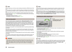 28
28 29
29 30
30 31
31 32
32 33
33 34
34 35
35 36
36 37
37 38
38 39
39 40
40 41
41 42
42 43
43 44
44 45
45 46
46 47
47 48
48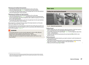 49
49 50
50 51
51 52
52 53
53 54
54 55
55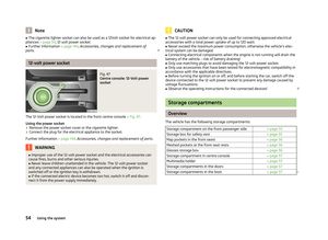 56
56 57
57 58
58 59
59 60
60 61
61 62
62 63
63 64
64 65
65 66
66 67
67 68
68 69
69 70
70 71
71 72
72 73
73 74
74 75
75 76
76 77
77 78
78 79
79 80
80 81
81 82
82 83
83 84
84 85
85 86
86 87
87 88
88 89
89 90
90 91
91 92
92 93
93 94
94 95
95 96
96 97
97 98
98 99
99 100
100 101
101 102
102 103
103 104
104 105
105 106
106 107
107 108
108 109
109 110
110 111
111 112
112 113
113 114
114 115
115 116
116 117
117 118
118 119
119 120
120 121
121 122
122 123
123 124
124 125
125 126
126 127
127 128
128 129
129 130
130 131
131 132
132 133
133 134
134 135
135 136
136 137
137 138
138 139
139 140
140 141
141 142
142 143
143 144
144 145
145 146
146 147
147 148
148 149
149 150
150 151
151 152
152 153
153 154
154 155
155 156
156 157
157 158
158 159
159 160
160 161
161 162
162 163
163 164
164 165
165 166
166 167
167 168
168 169
169 170
170 171
171 172
172 173
173 174
174 175
175 176
176 177
177 178
178 179
179