Page 249 of 289
248Emergencies
Note
● If it is not possible to tow the vehicle in the normal way, or if it has to be
towed further than 50 km (30 miles), it must be transported on a special car
transporter or trailer.
● Should the power supply to the selector lever be interrupted in posi-
tion P, the selector lever will be locked. Before the vehicle can be recovered/
manoeuvred you must manually release the selector lever ⇒ page 163.
Page 250 of 289
249
Fuses and bulbs
Fuses and bulbs Electrical fuses
Changing fuses
A blown fuse can be identified by the blown metal strip.
Fig. 131 Steering col-
umn area: cover
Fig. 132 Engine com-
partment, left-hand side:
fuse cover
Fuses in the steering column area
– Switch off the ignition and component concerned.
– Look in the tables below for the right fuse for the component
⇒ page 250.
– Remove the cover ⇒ Fig. 131.
– Remove the plastic clips from the fuse cover.
– Use the plastic clip to pull out the fuse and replace the blown
fuse with a fuse of the same rating.
Fuses in engine compartment
– Switch off the ignition and component concerned.
– Look in the tables below for the right fuse for the component
⇒ page 251.
Safety FirstOperating instructionsPractical TipsTechnical specifications
Page 251 of 289

250Fuses and bulbs
–Unlock the fuse cover ⇒ Fig. 132.
– Remove the clips from the fuse cover.
– Use the plastic clip to pull out the fuse and replace the blown
fuse with a fuse of the same rating.
The individual electrical circuits are protected by fuses. Fuses are located
under a cover below the steering wheel on the left side of the engine com-
partment.
WARNING
Do not repair fuses, and never replace a blown fuse with a higher amper-
age fuse. The electrical system could be damaged, with risk of fire.
CAUTION
● Multiple fuse values on the same line (for example, 5/10/20) in the fol-
lowing tables indicate equipment-related differences. Replace the blown
fuse with a fuse of the same amperage.
● If a newly replaced fuse blows again after a short time, the electrical sys-
tem must be checked by a specialised workshop as soon as possible.
Note
● Positions are not occupied by a fuse do not appear in the following ta-
bles.
● Some of the equipment listed in the tables below pertain only to certain
versions of the model or are an optional extra. Fuses in the vehicle interior
No.Electrical consumerAmpsF2Vacant-F4Alarm10F5Gateway5F6Anti-theft alarm system5
F7Air conditioner/heating control panel, selector
lever (automatic gearbox), relay coil, rear win-
dow heating, additional heating10
F8Diagnosis, handbrake switch, light switch, re-
verse light, interior lighting10
F9Vacant-F10Radio display10F11Vacant-F12Radio20F13Vacant-F14Air conditioner fan40F15Vacant-F16Vacant-F17Instrument panel5F18Vacant-F19Vacant-F20Vacant-F23Right lights40F24Sunroof30F25Left door30F26Heated seats30F27Vacant-F28Vacant-
Page 252 of 289

251
Fuses and bulbs
No.Electrical consumerAmpsF29Vacant-F30Vacant-F31Left lights40F32Parking aid control unit7,5F33Airbag5
F34Reverse switch, clima sensor, electrochromic
mirror7,5
F35Diagnosis, headlight control unit, headlight ad-
juster10
F36Front camera10F37Vacant-F38Vacant-F39Right door30F4012V socket20F41Steering column20F42Central locking40F43Interior light30F44Vacant-F45Vacant-F47Rear window wiper15F49Starter motor; clutch sensor5F51Vacant-F53Heated rear window30
The electric windows and electric seats* are protected by circuit breakers.
These switch on again automatically after a few seconds when the overload
(caused for example by frozen windows) has been corrected.
Note
Please note that the above list, while correct at the time of printing, is sub-
ject to alterations.
Fuses on left side of engine compartment
No.Electrical consumerAmpsF1Vacant-F2ESC control unit40F3Engine control unit (diesel/petrol)15/30F4Engine sensors5/10F5Engine sensors7,5/10F6Brake light sensor5F7Engine power supply5/10F8Lambda probe10F9Engine5/10/20F10Fuel pump control unit15/20F11PTC40F12PTC40F13Automatic gearbox control unit15/30F15Horn15F16Fuel pump control unit20F17Engine control unit7,5F18Terminal 30 (positive reference)5F19Front windscreen washer30F20Alarm horn10F22Engine control unit5F23Starter motor30
Safety FirstOperating instructionsPractical TipsTechnical specifications
Page 253 of 289

252Fuses and bulbs
No.Electrical consumerAmpsF24PTC40F31Vacant-F32Vacant-F37Vacant-
Note
Please note that the above list, while correct at the time of printing, is sub-
ject to alterations.
Bulbs
Changing a bulb
Changing bulbs requires a certain degree of practical skill. If you choose to change engine compartment lamps yourself, remember
that it is a dangerous area ⇒
in Working on components in the engine
compartment on page 209.
Always use identical bulbs with the same designation. The name can be
found on the base of the bulb holder.
Depending on how equipped the vehicle is, there are different sets of head-
lights and tail lights:
● Halogen headlights
● Full-LED main headlights*
● Rear bulb light
● LED rear light* Full-LED headlight system*
Full-LED headlights handle all light functions (daylight, side light, turn sig-
nal, dipped beam and route light) with light emitting diodes (LEDs) as a
light source.
Full-LED headlights are designed to last the lifetime of the car and light
bulbs cannot be replaced. In case of headlight failure, go to an authorised
workshop to have it replaced.
Bulbs (12 V)
Halogen headlightsTypeDaytime driving light/side lightP21W SLLDipped beam headlightsH7 LLMain beam headlightsH7 LLTurn signalPY21W LL
Full-LED main headlightsTypeNo bulbs may be replaced. All functions are
with LEDs
Front fog lightTypeFog light/cornering*H8
Rear bulb lightTypeBrake lights/tail lightsP21W LLSide lights2x W5W LLTurn signalPY21W LLRear fog lightH21WReverse lightsP21W LL
LED rear lightTypeTurn signalPY21W LLRear fog lightH21W
Page 254 of 289

253
Fuses and bulbs
LED rear lightTypeReverse lightsP21W LLThe remaining functions work with LEDs
WARNING
● Take particular care when working on components in the engine com-
partment if the engine is warm. Risk of burns.
● Bulbs are highly sensitive to pressure. The glass can break when you
touch the bulb, causing injury.
● When changing bulbs, please take care not to injure yourself on sharp
edges, in particular on the headlight housing.
CAUTION
● Remove the ignition key before working on the electric system. Other-
wise, a short circuit could occur.
● Switch off the lights or parking lights before you change a bulb.
● Take good care to avoid damaging any components.
For the sake of the environment
Please ask your specialist retailer how to dispose of used bulbs in the prop-
er manner.
Note
● Please check at regular intervals that all lighting (especially the exterior
lighting) on your vehicle is functioning properly. This is not only in the inter-
est of your own safety, but also that of all other road users.
● Before changing a bulb, make sure you have the correct new bulb.
● Do not touch the glass part of the bulb with your bare hands, use a cloth
or paper towel instead. Otherwise, the fingerprints left on the glass will va-
porise as a result of the heat generated by the bulb, they will be deposited
on the reflector and will impair its surface.
Safety FirstOperating instructionsPractical TipsTechnical specifications
Page 255 of 289
254Fuses and bulbs
Changing bulbs in headlight unit
Dipped beam bulb
Fig. 133 Dipped beam
headlights
Fig. 134 Dipped beam
headlights
– Raise the bonnet
– Move the loops ⇒ Fig. 133 1
in the direction of the arrow and
remove the cover.
– Remove connector ⇒ Fig. 134 2
from the bulb. –
Unclip the retainer spring ⇒ Fig. 134 3
pressing inwards to the
right.
– Extract the bulb and fit the replacement so that the rim of the
attachment plate is on the reflector cut-out.
Daylight bulb
Fig. 135 Daylight bulb
– Raise the bonnet.
– Turn bulb holder ⇒ Fig. 135 A
to the left and pull.
– Remove the bulb by pressing on the bulb holder and turning it
anti-clockwise at the same time.
– Installation involves all of the above steps in reverse sequence.
Page 256 of 289
255
Fuses and bulbs
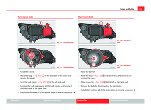
Turn signal bulb
Fig. 136 Turn signal bulb
Fig. 137 Turn signal bulb
– Raise the bonnet
– Move the loop ⇒ Fig. 136 1
in the direction of the arrow and
remove the cover.
– Turn the bulb holder ⇒ Fig. 137 2
to the left and pull.
– Remove the bulb by pressing on the bulb holder and turning it
anti-clockwise at the same time.
– Installation involves all of the above steps in reverse sequence. Main beam bulb
Fig. 138 Main beam
bulb
Fig. 139 Main beam
bulb
– Raise the bonnet
– Move the loop ⇒ Fig. 138 1
in the direction of the arrow and
remove the cover.
– Slide connector ⇒ Fig. 139 2
to the left or right and pull.
– Remove the bulb by disconnecting the connector.
– Installation involves all of the above steps in reverse sequence.
Safety FirstOperating instructionsPractical TipsTechnical specifications