Page 342 of 442

For emergencies
6-3
6
2. Position the vehicles close enough together so that the
jumper cables can reach, but be sure the vehicles are not
touching each other.
3. Set the parking brake firmly on your vehicle and move the
selector lever into the “P” (PARK) position.
4. Set the parking brake firmly on the other vehicle. Put the
automatic transaxle in “P” (PARK) or the manual
transaxle in “N” (Neutral).
5. Turn the ignition switch (the electric motor switch) on
each vehicle to the “LOCK” position.NOTE�Turn off all lights, heater, and other electrical loads. This
will help avoid sparks.6. Remove the battery cover, and then make sure your 12V
starter battery electrolyte is at the proper level. (Refer to
“Checking 12V starter battery electrolyte level” on page
7-14.)
7. Connect one end of one jumper cable to the positive
(+) terminal of the discharged battery (A), and then con-
nect the other end to the positive (+) terminal of the
booster battery (B).
CAUTION
!�Check the other vehicle. It must have a 12V battery.
If the other system is not 12V, both systems can be
damaged.
WA R N I N G
!�If the electrolyte fluid is not visible, or looks frozen,
DO NOT ATTEMPT JUMP STARTING!!
The battery might split open or explode if the tem-
perature is below the freezing point or if it is not
filled to the proper level.
BK0140800US.book 3 ページ 2011年9月29日 木曜日 午後3時28分
Page 394 of 442

Vehicle care and maintenance
7-31
7
*: Fusible link
�Some fuses may not be installed on your vehicle, depend-
ing on the vehicle model or specifications.
�The table above shows the main equipment corresponding
to each fuse.
No.
Symbol
Electrical system
Capacity
1 Tail light (left) 7.5 A
2Cigarette lighter/
12 V power outlet15 A
3 — — —
4Starter 7.5 A
5 Audio amplifier 20 A
6— — —
7 Tail light (right) 7.5 A
8 Outside rearview mirrors 7.5 A
9Control unit
(Electric motor unit)7.5 A
10 Control unit 7.5 A
11 Rear fog light 10 A
12 Door lock 15 A
13 Interior lights (Dome lights) 10 A
14 Rear window wiper 15 A
15 Gauges 7.5 A
16 Relay 7.5 A
17 Heated seat 20 A
18 Option 10 A
19Heated door outside rearview
mirrors7.5 A
20 Windshield wiper 20 A
21 Back-up lights 7.5 A
22 Defogger 30 A
23 Heater 30 A
24 12V starter battery 30 A*
25 Radio 10 A
26 Electronic controlled unit 15 A
27 — Electronic controlled unit 7.5 ANo.
Symbol
Electrical system
Capacity
BK0140800US.book 31 ページ 2011年9月29日 木曜日 午後3時28分
Page 395 of 442

7-32 Vehicle care and maintenance
7
Under the hood fuse location table
*: Fusible link
�Some fuses may not be installed on your vehicle, depend-
ing on the vehicle model or specifications.
�The table above shows the main equipment corresponding
to each fuse.
No.
Symbol
Electrical system
Capacity
1— — —
2 12V starter battery 30 A*
3 Electric motor switch 40 A*
4 Radiator fan motor 40 A*
5 Power window control 40 A*
6 Brake electric vacuum pump 30 A*
7 Electric motor unit control 15 A
8 Stop lights (Brake lights) 15 A
9 Front fog lights 15 A
10Wa t e r p u m p
(Electric motor unit)15 A
11 Charge 10 A
12 Hazard warning flasher 10 A
13 Horn 10 A
14 Daytime running lights 10 A
15Main drive lithium-ion bat-
tery fan motor15 A
16Wa t e r p u m p
(Air conditioning)10 A
17 Headlight (low beam) (right) 20 A
18 Headlight (low beam) (left) 20 A
19 Headlight (high beam) (right) 10 A
20 Headlight (high beam) (left) 10 ANo.
Symbol
Electrical system
Capacity
BK0140800US.book 32 ページ 2011年9月29日 木曜日 午後3時28分
Page 400 of 442
Vehicle care and maintenance
7-37
7
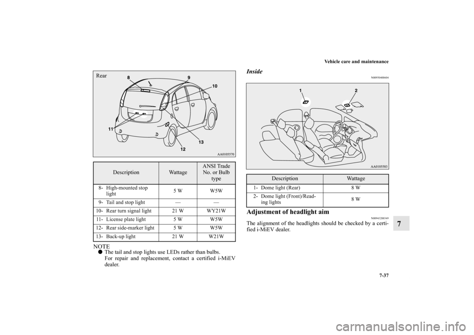
NOTE�The tail and stop lights use LEDs rather than bulbs.
For repair and replacement, contact a certified i-MiEV
dealer.
Inside
N00950400604
Adjustment of headlight aim
N00943200349
The alignment of the headlights should be checked by a certi-
fied i-MiEV dealer.
Description
Wattage
ANSI Trade
No. or Bulb
type
8- High-mounted stop
light5 W W5W
9- Tail and stop light — —
10- Rear turn signal light 21 W WY21W
11- License plate light 5 W W5W
12- Rear side-marker light 5 W W5W
13- Back-up light 21 W W21WRear
Description
Wattage
1- Dome light (Rear) 8 W
2- Dome light (Front)/Read-
ing lights8 W
BK0140800US.book 37 ページ 2011年9月29日 木曜日 午後3時28分
Page 401 of 442
7-38 Vehicle care and maintenance
7
Front side-marker lights
N00915500161
1. Insert a flat blade screwdriver into the end of the light
nearer the rear of the body and pry gently to remove the
light.NOTE�Wrap a cloth around the tip of the screwdriver to keep
from scratching the lens.2. Remove the socket and bulb assembly together by turning
it counterclockwise.*: Front of the vehicle
*
BK0140800US.book 38 ページ 2011年9月29日 木曜日 午後3時28分
Page 403 of 442
7-40 Vehicle care and maintenance
7
Front turn signal lights/Front fog lights (if so
equipped)/Daytime running lights
(if so equipped)
N00943400312
1. To create enough work space, turn the steering wheel all
the way in the same direction to the side you wish to
replace.
2. Remove the clip (A) and bolts (B), then lift the cover (C).3. Turn the socket counterclockwise to remove it.
D- Front turn signal light
E- Front fog light
F- Daytime running light
BK0140800US.book 40 ページ 2011年9月29日 木曜日 午後3時28分
Page 404 of 442
Vehicle care and maintenance
7-41
7
4. Remove the bulb as follows.
[Front turn signal light]
Pull the bulb out of the socket.
[Front fog light and daytime running light]
While holding down the tab (F), pull out the bulb assem-
bly (G).5. To install the bulb, perform the removal steps in reverse.Front fog light
Daytime running light Front turn signal light
CAUTION
!�Handle halogen light bulb with care. The gas inside
a halogen light bulb is highly pressurized, so drop-
ping, knocking, or scratching a halogen light bulb
can cause it to shatter.�Never hold the halogen light bulb with a bare hand,
dirty glove, etc.
The oil from your hand could cause the bulb to
break the next time the fog lights are used.
If the glass surface is dirty, clean it with alcohol and
let it dry completely before installing the bulb.
BK0140800US.book 41 ページ 2011年9月29日 木曜日 午後3時28分
Page 405 of 442
7-42 Vehicle care and maintenance
7
Rear combination lights
N00943700487
1. Open the liftgate.
(Refer to “Liftgate” on page 3-16.)
2. Remove the screws (A) that hold the light unit and remove
the light unit.3. Move the light unit toward the rear of the vehicle and
remove the pins (B) of the light unit from the vehicle.
BK0140800US.book 42 ページ 2011年9月29日 木曜日 午後3時28分

/Daytime running lights
(if so equipped)
N00943400312
1. To create enough work space, turn the steering")
![MITSUBISHI iMiEV 2012 1.G Owners Manual Vehicle care and maintenance
7-41
7
4. Remove the bulb as follows.
[Front turn signal light]
Pull the bulb out of the socket.
[Front fog light and daytime running light]
While holding down the tab (F)](/manual-img/19/7553/w960_7553-403.png "MITSUBISHI iMiEV 2012 1.G Owners Manual Vehicle care and maintenance
7-41
7
4. Remove the bulb as follows.
[Front turn signal light]
Pull the bulb out of the socket.
[Front fog light and daytime running light]
While holding down the tab (F)")

2. Remove the screws (A) that hold the light unit and remove
the")