Page 201 of 378

To temporarily increase or decrease
the speed
E00609600178
To temporarily increase the speed
Depress
the accelerator pedal as you would normal-
ly. When you release the pedal, you will return to
your set speed. NOTE
l In
some driving conditions, the set speed driv-
ing may be deactivated. If this happens, refer
to “To activate” on page 4-45 and repeat the
speed setting procedure. To temporarily decrease the speed
Depress
the brake pedal to decrease the speed. To
return to the previously set speed, press the “ACC
RES” switch (C). Refer to “To resume the set
speed” on page 4-48. To deactivate
E00609701206
The set speed driving can be deactivated as follows:
l Press
the “ON OFF” switch (A) (Cruise con-
trol will be turned off)
l Press the “CANCEL” switch (D).
l Depress the brake pedal. The set speed driving is deactivated automatically
in any of the following ways.
l When
you depress the clutch pedal (on vehi-
cles with M/T).
l When your speed slows to about 15 km/h
(9 mph) or more below the set speed because
of a hill, etc.
l When your speed slows to about 40 km/h
(25 mph) or less.
l When the Active Stability Control (ASC)
starts operating. (if so equipped)
Refer to “Active stability control (ASC)” on
page 4-42. WARNING
l On
vehicles equipped with CVT, al-
though the set speed driving will be deac-
tivated when shifting to the “N” (NEU-
TRAL) position, never move the selector
lever to the “N” (NEUTRAL) position
while driving.
You would have no engine braking and
could cause a serious accident.
Also, the set speed driving may be deactivated as
follows: l When
the engine speed rises and approaches
the tachometer's red zone (the red-coloured
part of the tachometer dial). Starting and driving
4-47 4
OGWE12E1
Page 202 of 378

CAUTION
l
When the set speed driving is deactivated
automatically in any situation other than
those listed above, there may be a system
malfunction.
Press the “ON-OFF” switch to turn off
the cruise control and have your vehicle
inspected by a MITSUBISHI MOTORS
Authorized Service Point.
To resume the set speed E00609800617
If the set speed driving is deactivated by the condi-
tion
described in “To deactivate” on page 4-47,
you can resume the previously set speed by press-
ing the “ACC RES” switch (C) while driving at a
speed of about 40 km/h (25 mph) or higher. Under either of the following conditions, however,
using
the switch does not allow you to resume the
previously set speed.
In these situations, repeat the speed setting proce-
dure:
l The “ON OFF” switch is pressed. l
[Except
vehicles equipped with keyless oper-
ation system]
Turn the ignition switch to the “LOCK” or
“ACC” position.
Put the operation mode in OFF or ACC.
l “CRUISE” indication lamp is turned OFF. Reversing sensor system*
E00615500345
This
system operates when you are backing the ve-
hicle. It uses corner and back sensors to detect an
obstacle and the information screen in the multi-in-
formation display and the buzzer to inform you of
the approximate distance to the obstacle. CAUTION
l
The reversing sensor system assists you in
determining the approximate distance be-
tween
the vehicle and an obstacle located
behind the vehicle. It has limitations in
terms of detectable areas and objects,
and may not properly detect some ob-
jects. Therefore, do not place excessive
confidence in the reversing sensor system
and operate the vehicle as carefully as
you would do with a vehicle not equipped
with this system.
l Make sure to check the surroundings
with your own eyes to ensure safety. Do
not operate the vehicle by relying on the
reversing sensor system alone.
Obstacle detection areas E00615600346
The detection areas of the corner and back sensors
are
limited to those shown in the illustration. More-
over, the sensors are unable to detect low or thin ob-
jects or objects near the rear bumper. Thus, make
sure to check the surroundings as you operate the
vehicle in a safe manner. Starting and driving
4-48
4
OGWE12E1
Page 203 of 378

Corner and back sensor locations
There
are two corner sensors (A) at the corners of
the rear bumper, and two back sensors (B) in the
centre of the rear bumper. Reversing sensor system detection areas
Depending
on whether the vehicle is equipped with
a towing bar, you can change the reversing sensor
system between the standard mode and the towing
bar mode. The towing bar mode changes the sys-
tem to exclude the area in which the towing bar is
mounted from the detection areas. Vehicles without a towing bar
The
detection areas are within approximately
60 cm (A) from the corner sensors, 150 cm (B)
from the back sensors, and 60 cm (C) or less from
the ground surface, excluding the area approximate-
ly 10 cm (D) from the ground surface. Vehicles with a towing bar
The
detection areas are within approximately
60 cm (A) from the corner sensors, 150 cm (B)
from the back sensors, and 60 cm (C) or less from
the ground surface, excluding the area approximate-
ly 10 cm (D) from the ground surface. The non-de-
tection areas (E) are within approximately 20 cm
(F) from the bumper. NOTE
l If
the rear bumper has been exposed to an im-
pact, the corner or back sensors may fail and
prevent the system from functioning proper-
ly. Have the vehicle inspected at a
MITSUBISHI MOTORS Authorized Service
Point.
l The sensors do not detect objects located in
the area directly below or near the bumper. If
the height of an object is lower than the moun-
ted position of the corner or back sensors,
the sensors may not continue detecting it
even if they detected it initially.
For information on how to change the detection
areas, please refer to “Changing the detection
areas” on page 4-51. Starting and driving
4-49 4
OGWE12E1
Page 204 of 378

CAUTION
l
The reversing sensor system may not op-
erate properly under the following condi-
tions: • The sensors or surroundings are cov-ered with ice, snow, or mud.
• The sensors are frozen.
• The system receives ultrasonic noise from other sources (the horns of other
vehicles, motorcycle engines, brakes,
radios, pouring rain, splashing water,
tyre chains, etc.).
• The sensors are extremely hot or cold (while the vehicle is parked for a long
period of time under a blazing sun or
in cold weather).
• The vehicle tilts significantly.
• The vehicle is driven on a rough road (with a bumpy, gravel, hilly, or grassy
surface).
• The vehicle is too close to an obstacle.
• The sensors or surroundings have been wiped by hand, or stickers or ac-
cessories have been attached.
l The reversing sensor system may not prop-
erly detect the following:
• Objects that are thin, such as wirenets or ropes.
• Objects that absorb sound waves, such as snow.
• Objects that are shaped with a sharp angle.
• Objects with a smooth surface, such as glass.
• Objects that are low, such as kerb- stones. NOTE
l The
buzzer may sound lower than the normal
warning sound when the reversing sensor sys-
tem is receiving ultrasonic noise from other
sources, but this is not a malfunction. The buz-
zer will stop sounding and the system will re-
turn to normal operation after the noise is no
longer received.
To operate E00615700738
To operate the system, move the gearshift lever or
selector
lever to the “R” position while the ignition
switch or the operation mode is in ON. When the
reversing sensor system is operated, the reversing
sensor system operation indication lamp (A) will
turn on. To stop the operation, push the “SONAR”
switch; the reversing sensor system operation indi-
cation lamp (A) is turned off. NOTE
l Only
when the gearshift lever or selector lev-
er is in the “R” position, the reversing sensor
system can be operated or be stopped by us-
ing the “SONAR” switch.
Warning for obstacles
If there is an obstacle behind the vehicle, a warning
will be issued with the information screen in the
multi-information display and a warning buzzer.
Type 2
Type 1 1- Corner sensor (left)
2-
Back sensor
3- Corner sensor (right)
Corner sensor Vehicle to obstacle dis-
tance Warning display/sound
cycle
Approx. 60 to 40 cm Intermittent
Approx. 40 to 20 cm Fast intermittent
Within approx. 20 cm Continuous Starting and driving
4-50
4
OGWE12E1
Page 205 of 378

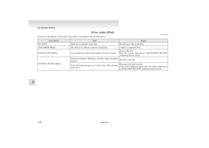
Back sensor (vehicles without a towing bar)
Vehicle to obstacle dis-
tance Warning display/sound
cycle
Approx. 150 to 80 cm Intermittent Approx. 80 to 40 cm Fast intermittent
Within approx. 40 cm Continuous Back sensor (vehicles with a towing bar)
Vehicle to obstacle dis-
tance Warning display/sound
cycle
Approx. 150 to 100 cm Intermittent Approx. 100 to 60 cm Fast intermittentWithin approx. 60 cm Continuous CAUTION
l
The distances given are to be used for ref-
erence
only, as errors may be caused by
various factors, such as temperature, hu-
midity, or the shape of the obstacles.
NOTE l When
the sensors detect different obstacles
at the same time, the information screen in
the multi-information display indicates the di-
rections of the obstacles each sensor is detect-
ing. However, closer obstacles are given pri-
ority over other detected obstacles and the
warning buzzer sounds to inform you of clos-
er obstacles. Changing the detection areas
E00615800159
The detection areas can be changed as follows:
Vehicles with a towing bar
While
the operation of the system is stopped at the
“SONAR” switch, push the “SONAR” switch ap-
proximately 3 seconds or more, and release it. The
buzzer sounds twice to indicate that the detection
area has been changed.
Vehicles without a towing bar
While the operation of the system is stopped at the
“SONAR” switch, push the “SONAR” switch ap-
proximately 3 seconds or more, and release it. The
buzzer sounds once to indicate that the detection
area has been changed.
NOTE
l The detection area will not change if you
keep the “SONAR” switch pushed for
10 seconds or more.
l After pushing the “SONAR” switch, revers-
ing sensor system operation differs accord-
ing to the detection area setting.
• Setting when towing bar is not equippedWhen the gearshift lever or selector lever
is moved to the “R” position, the revers-
ing sensor system will operate even if cor-
ner sensor operation was stopped by push-
ing the “SONAR” switch. • Setting when towing bar is equipped
When reversing sensor system operation
was stopped by pushing the “SONAR”
switch, the reversing sensor system will
not operate until the engine has been stop-
ped even if the gearshift lever or selector
lever is moved to the “R” position.
To resume reversing sensor system opera-
tion, push the “SONAR” switch or stop
and restart the engine, and then move the
gearshift lever or selector lever to the “R”
position.
Reversing sensor system warning dis-
play E00615900277
In case there is a malfunction in the reversing sen-
sor
system, the display for the malfunctioning sen-
sor will blink and the warning buzzer will sound
for approximately 5 seconds. Even after the buzzer
has stopped sounding, the display will continue
blinking until the system reverts to the normal
state. Have the vehicle inspected at a
MITSUBISHI MOTORS Authorized Service Point.
Example: Corner sensor (left) mulfunctioning
Type 2
Type 1 Starting and driving
4-51 4
OGWE12E1
Page 206 of 378

Rear-view camera*
E00618400257
The
rear-view camera is a system that shows the
view behind the vehicle on the screen of the
MITSUBISHI Multi Communication System
(MMCS) or the inside rear-view mirror. CAUTION
l
The
rear-view camera is an assistance sys-
tem that enables the driver to check for
obstacles behind the vehicle. Its range of
view is limited, so you should not overly
depend on it. Please drive just as careful-
ly as you would if the vehicle did not have
the rear-view camera.
l Be sure to visually confirm safety around
the vehicle with your own eyes. Do not de-
pend entirely on the rear-view camera.
Range of view of rear-view camera
The
range of view of the rear-view camera is limi-
ted to the area shown in the illustrations. It cannot
show both sides and the lower part of the rear bump-
er, etc.
When reversing, be sure to visually confirm safety
around the vehicle. Location of rear-view camera
The rear-view camera (A) is integrated into the part
near the tailgate handle.
Range of view of rear-view camera How to use the rear-view camera
When you place the gearshift lever or selector lever
in
the “R” position with the ignition switch or the
operation mode in ON, the view behind the vehicle
will automatically appear on the screen of the
MITSUBISHI Multi Communication System
(MMCS) or the inside rear-view mirror. When you
move the gearshift lever or the selector lever to any
other position, the screen will return to its original
indication. CAUTION
l
The
rear-view camera has a special lens
that can make objects shown on the
screen appear to be closer or further
away than they actually are.
NOTE l Because
the rear-view camera has a special
lens, the lines on the ground between parking
spaces may not look parallel on the screen. Starting and driving
4-52
4
OGWE12E1
Page 207 of 378

l
In the following situations, the screen indica-
tion may be difficult to see. There is no ab-
normality. • Low light (nighttime)
• When the light of the sun or the lightfrom a vehicle’s headlamps shines direct-
ly into the lens
l If the camera is hot and is then cooled by
rain or a car wash, the lens can mist up. This
phenomenon does not indicate a malfunction.
l It is not possible to fully see obstacles when
the lens is dirty. If the lens becomes contami-
nated by water droplets, snow, mud or oil,
wipe off the contamination, taking care not
to scratch the lens.
l Please observe the following cautions. Ignor-
ing them could lead to a camera malfunction.
• Do not subject the camera to physicalshock.
• Do not apply wax to the camera.
• Do not splash the camera with boiling wa- ter.
• Do not disassemble the camera.
Reference lines on the screen
Reference lines and upper surface of the rear bump-
er (A) are displayed on the screen. l Red line (B) indicates approximately 50 cm
behind the rear bumper.
l Two Green lines (C) indicate approximately
20 cm outside of the vehicle body.
l Short transverse lines (1 to 3) indicate dis-
tance from the rear bumper.
Check surroundings for safety. 1. Approximately
at the rear edge of the rear
bumper
2. Approximately 100 cm
3. Approximately 200 cm
NOTE l It is possible to change the display language
of the screen. For details, please refer to the
separate owner’s manual “MITSUBISHI
Multi Communication System (MMCS)”or
“To change the indication on the screen of
the inside rear-view mirror: To change the lan-
guage of warning text (3)” on page 4-54.
l When the vehicle is tilting because of the num-
ber of people in the vehicle, the weight and
positioning of luggage, and/or the condition
of the road surface, the lines in the view
from the rear-view camera may not be accu-
rately positioned relative to the actual road.
The reference lines for distance and vehicle
width are based on a level, flat road surface.
In the following cases, objects shown on the
screen will appear to be farther off than they
actually are. • When
the rear of the vehicle is weighed
down with the weight of passengers and
luggage in the vehicle. A- Actual objects
B-
Objects shown on the screen
• When there is an upward slope at the back. A- Actual objects
B-
Objects shown on the screen
Starting and driving
4-53 4
OGWE12E1
Page 208 of 378

l
The reference lines for distance and vehicle
width are intended to indicate the distance to
a flat object such as a level, flat road surface.
This may make the distance to a projecting
object shown on the screen differ from the ac-
tual distance to the projecting object. Do not
use them as a guide for distances to solid ob-
jects.
Example: On the screen the point B appears
the nearest, then the point C and A in order
of distance. The points A and B actually are
the same distances from the vehicle, and the
point C is farther off than the points A and B.
Check surroundings for safety. To change the indication on the screen
of the inside rear-view mirror
E00631300093
It
is possible to turn off the screen of the inside rear-
view mirror and change the language of the warn-
ing messages on the screen. To temporarily set the non- display mode
If
you press the switch (1) while the image appears
on the display, it goes off temporarily.
To return to the display mode, press the switch
again or perform the following operation.
[Except for vehicles equipped with keyless opera-
tion system]
Turn the ignition switch to the “ON” position after
turning to the “LOCK” or “ACC” position.
[For vehicles equipped with keyless operation sys-
tem]
Put the operation mode in ON after putting the op-
eration mode in OFF.
To permanently set the non- display mode
1. Turn the ignition switch to the “ON” posi-tion or put the operation mode in ON. CAUTION
l
For
safety reasons, do not perform follow-
ing operations with the engine running.
2. Put
the gearshift lever or the selector lever in the “R” position.
3. Press and hold down the switch (1) (for about 15 seconds).
While you keep the switch pressed, the or-
ange indicator (2) comes on. When the im-
age goes off, the non-display mode setting is
completed.
To change the language of warning text(3) 1. Turn the ignition switch to the “ON” posi-tion or put the operation mode in ON. CAUTION
l
For
safety reasons, do not perform follow-
ing operations with the engine running.
2. Put
the gearshift lever or the selector lever in the “R” position.
3. Press and hold down the switch (1) to enter language selection mode (for 6 to 11 seconds).
In this mode, the image appears and the
green indicator (2) comes on.
4. Press the switch until the desired language ap- pears on the display.
Each time you press the switch, the language
will change to the next one. When the warn-
ing text flashes, setting is completed. Starting and driving
4-54
4
OGWE12E1