2012 MERCEDES-BENZ CLS COUPE steering
[x] Cancel search: steeringPage 323 of 373
X
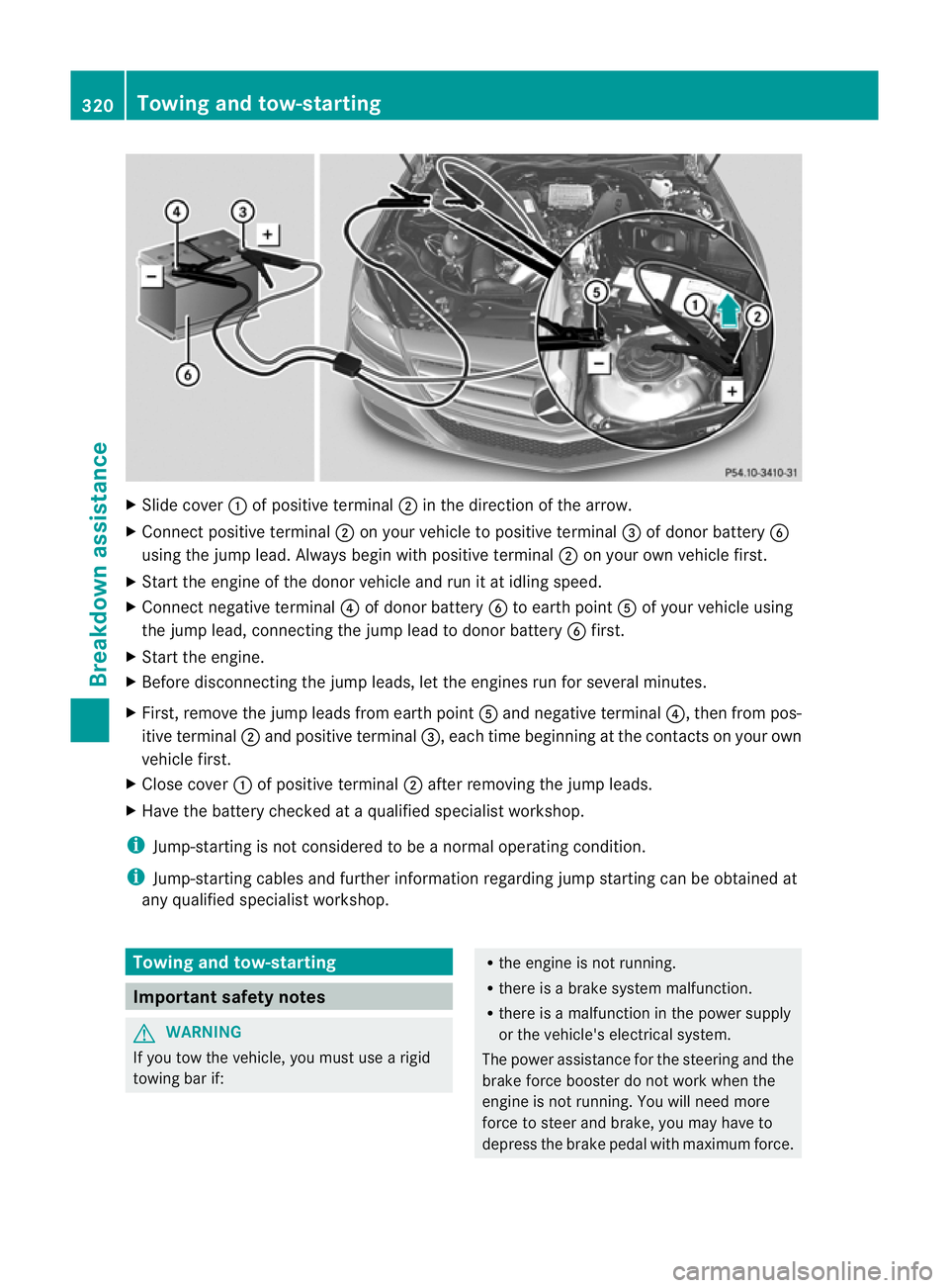
Slide cover :of positive terminal ;in the direction of the arrow.
X Connect positive terminal ;on your vehicl etopositive terminal =of dono rbattery B
using the jump lead .Always begin with positive terminal ;on your own vehicle first.
X Start the engine of the dono rvehicle and run it at idling speed.
X Connec tnegativ eterminal ?of donor battery Bto earth point Aof your vehicle using
the jump lead, connectingt he jump lead to donor battery Bfirst.
X Start the engine.
X Before disconnecting the jump leads, let the engines run for several minutes.
X First, remove the jump leads from earth point Aand negative terminal ?,then from pos-
itive terminal ;and positive terminal =,each time beginning at the contacts on your own
vehicle first.
X Close cover :of positive terminal ;after removing the jump leads.
X Have the battery checked at aqualified specialist workshop.
i Jump-starting is not considered to be anormal operating condition.
i Jump-starting cables and further information regarding jump startingc an be obtained at
any qualified specialist workshop. Towing and tow-starting
Important safety notes
G
WARNING
If you tow the vehicle, you must use arigid
towing bar if: R
the engine is not running.
R there is abrake system malfunction.
R there is amalfunction in the power supply
or the vehicle's electrical system.
The power assistance for the steering and the
brake force booster do not work when the
engine is not running. You will need more
force to steer and brake, you may have to
depress the brake pedal with maximum force. 320
Towing and tow-startingBreakdown assistance
Page 325 of 373
particularly careful when removing the rear
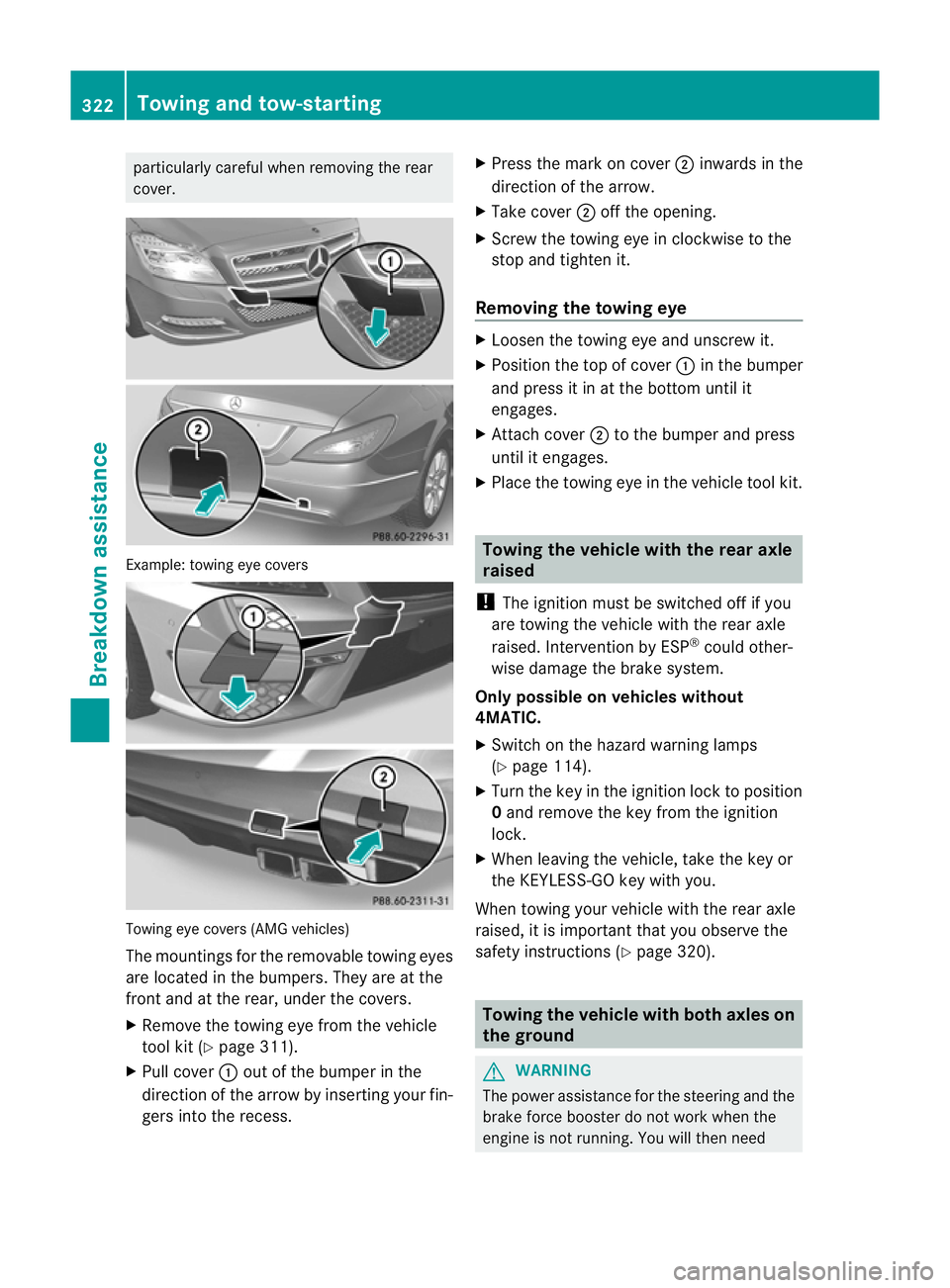
cover. Example: towing eye covers
Towing eye cover
s(AMG vehicles)
The mountings for the removable towing eyes
are located in the bumpers. They are at the
fron tand at the rear, under the covers.
X Remove the towing eye from the vehicle
tool kit (Y page 311).
X Pull cover :out of the bumper in the
direction of the arrow by inserting your fin-
gers int othe recess. X
Press the mark on cover ;inwards in the
direction of the arrow.
X Take cover ;off the opening.
X Screw the towing eye in clockwise to the
stop and tighten it.
Removing the towing eye X
Loosen the towing eye and unscrew it.
X Position the top of cover :in the bumper
and press it in at the bottom until it
engages.
X Attach cover ;to the bumper and press
until it engages.
X Place the towing eye in the vehicle tool kit. Towing the vehicle with the rear axle
raised
! The ignition must be switched off if you
are towing the vehicle with the rear axle
raised. Intervention by ESP ®
could other-
wise damage the brake system.
Only possible on vehicles without
4MATIC.
X Switc hont he hazard warning lamps
(Y page 114).
X Turn the key in the ignition lock to position
0and remov ethe key from the ignition
lock.
X When leaving the vehicle, take the key or
the KEYLESS-GO key with you.
When towing your vehicle with the rear axle
raised, it is important that you observe the
safety instructions (Y page 320). Towing the vehicle with both axles on
the ground
G
WARNING
The power assistance for the steering and the
brake forc ebooster do not work when the
engin eisnot running. You will then need 322
Towing and tow-startingBreakdown assistance
Page 326 of 373
much more effort to brake and steer the vehi-
cle. Adapt yours tyleofd rivingaccordingly.
It is important tha tyou observe the safety
instructions when towing away your vehicle
(Y page 320).
The automatic transmission automatically
shifts to position Pwhen you open the driver's
or front-passenger door or when you remove
the key from the ignition lock. In order to
ensure that the automatic transmission stays
in position Nwhen towing the vehicle, you
must observe the following points:
X Make sure that the vehicle is stationary and
that the key is in position 0in the ignition
lock.
X Turn the key to position 2in the ignition
lock.
On vehicles with KEYLESS-GO, use the key
instead of the Start/Stop button
(Y page 141).
X Depress and hold the brake pedal.
X Shift the automatic transmission to posi-
tion N.
X Release the brake pedal.
X Release the parking brake.
X Switch on the hazard warning lamps
(Y page 114).
X Leave the key in position 2in the ignition
lock.
i When towing with the hazard warning
lamps switched on, use the combination
switch as usual to signal achange of direc-
tion. In this case, only the turn signals for
the desired direction flash. When the com-
bination switch is reset, the hazard warning
lamps start flashing again. Transporting the vehicle
! Only lash the vehicle down by the wheels
or wheel rims, not by parts of the vehicle
such as axle or steering components. Oth-
erwise, the vehicle could be damaged. The towing eye can be used to pull the vehicle
onto atrailer or transporter for transporting
purposes.
X Turn the key to position 2in the ignition
lock.
X Shift the automatic transmission to posi-
tion N.
As soon as the vehicle is loaded:
X Prevent the vehicle from rolling away by
applying the parking brake.
X Shift the automatic transmission to posi-
tion P.
X Turn the key in the ignition lock to position
0and remove the key from the ignition
lock.
X Secure the vehicle. Notes for 4MATIC vehicles
! Vehicles with 4MATIC must not be towed
with the front or rear axle raised; otherwise,
the transmission may be damaged.
If the vehicle has transmission damage or
damage to the front or rear axle, have it trans-
ported on atransporter or trailer.
In the event of damage to the electrical
system
If the battery is defective, the automatic
transmission will be locked in position P.To
shift the automatic transmission to position
N,y ou must provide power to the vehicle's
electrical system in the same way as when
jump-starting (Y page 319).
Have the vehicle transported on atransporter
or trailer. Tow-starting (emergency engine
starting)
! Vehicles with automatic transmission
must not be tow-started. The transmission
may otherwise be damaged. Towing and tow-starting
323Breakdown assistance Z
Page 334 of 373
Snow chains
G
WARNING
If you have fitted snow chains to the front
wheels, they may scrape against the vehicle
body or chassis components. This could
cause damage to the vehicle or the tyres.
There is arisk of an accident.
To avoid hazardous situations:
R never fit snow chains on the front wheels
R fit snow chains to the rear wheels in pairs.
For safety reasons, Mercedes-Benz recom-
mends that you only use snow chains that
have been specially approved for your vehicle
by Mercedes-Benz, or that are of acorre-
sponding standard of quality.
If you intendtof it snow chains, please bear
the following points in mind:
R snow chains cannot be fitted to all wheel-
tyre combinations. Permissible wheel-tyre
combination s(Ypage 341).
R only use snow chains when the road sur-
face is completely snow-covered. Remove
the snow chains as soon as possible when
you come to aroad that is not snow-cov-
ered.
R local regulations may restrictt he use of
snow chains. Observe the appropriate reg-
ulations if you wish to fit snow chains.
R do not exceed the maximum permissible
speed of 50 km/h.
R on vehicles with AIRMATIC, you must drive
at raised vehicle level if snow chains have
been fitted (Y page 181).
i You may wish to deactivate ESP ®
when
pulling away with snow chains fitted
(Y page 66). This way you can allow the
wheels to spin in acontrolled manner, ach-
ieving an increased driving force (cutting
action).
For more information on driving with an emer-
gency spare wheel, see (Y page 351). Tyrep
ressure Tyrep
ressur especifications G
WARNING
Tyres with too low or too high tyre pressure
contain the following hazards:
R they can burst, in particular if the vehicle is
heavily laden or when driven at high
speeds.
R the tyres can wear excessively and/or
unevenly, which can severely impair tyre
traction.
R the driving, steering and braking character-
istics may be severely impaired.
There is arisk of accident.
Follow recommended tyre inflation pressures
and check the pressure of all the tyres includ-
ing the spare wheel:
R at least every two weeks
R if the load changes
R before beginning along journey
R for changed operating conditions, e.g. off-
road driving
If necessary, correct the tyre pressure. G
WARNING
If you fit unsuitable accessories onto tyre
valves, the tyre valves may be overloaded and
malfunction, which can cause tyre pressure
loss. Due to their design, retrofitted tyre pres-
sure monitors keep the tyre valve open. This
can also result in tyre pressure loss. There is
ar isk of accident.
Only screw standard valve caps or valve caps
specifically provided by Mercedes-Ben zfor
your vehicle onto the tyre valve. G
WARNING
If the tyre pressure drops repeatedly, the
wheel, valve or tyre may be damaged. Tyre
pressure that is too low may result in atyre
blow-out. There is arisk of accident. Tyrep
ressure
331Wheels and tyres
Z
Page 336 of 373
message willa
ppear in the multifunction dis-
play.
The tyre pressure warning system does not
warn you of an incorrectly set tyre pressure.
Observe the notes on the recommended tyre
pressure (Y page331).
The tyre pressure loss warning system does
not replace the need to regularl ycheck your
vehicle's tyre pressures, since an even loss of
pressure on severa ltyres at the same time
cannot be detected by the tyre pressure loss
warning system.
The tyre pressure monitor is not abletow arn
you of asudden loss of pressure, e.g. if the
tyre is penetrated by aforeig nobject. In the
event of asudden loss of pressure, bring the
vehicl etoah altbybrakingcarefully. Avoid
abrupt steerin gmanoeuvres.
The function of th etyrep ressur elos sw arning
system is limite dordelayedif:
R snow chains are fitted to you rvehicle's
tyres.
R road conditions are wintry.
R you are driving on sand or gravel.
R you adopt avery sport ydriving style (cor-
nerin gath igh speeds or driving with high
rates of acceleration).
R you are driving with aheavy load (in the
vehicle or on the roof).
Restarting the tyrep ressure loss warn-
ing system Restart the tyre pressure loss warning system
if you have:
R changed the tyre pressure
R changed the wheels or tyres
R fitted new wheels or tyres
X Befor erestarting, make sure that the tyre
pressures are set properly on all four tyres
for the respective operatin gconditions.
The recommended tyre pressures can be
found in the table on the fuel filler flap. The
tyre pressure loss warning system can only
give reliable warnings if you have set the correct tyre pressure. If an incorrect tyre
pressure is set, these incorrect values will
be monitored.
X Also observe the notes in the section on
tyre pressures (Y page 331).
X Make sure that the key is in posi-
tion 2(Ypage 141)int he ignition lock.
X Press =or; on the steering wheel
to select the Serv. menu.
X Press the 9or: button to select
Tyre pressure .
X Press the abutton.
The Run Flat Indicator active Restart with OK message appears in the
multifunction display.
If you wish to confirm the restart:
X Press button a.
The Tyre press. now OK? message
appears in the multifunction display.
X Press the 9or: button to select
Yes .
X Press the abutton.
The Run Flat Indicator restarted message appears in the multifunction dis-
play.
After
ateach-in period, the tyre pressure
loss warning system will monitor the set
tyre pressures of all four tyres.
If you wish to cancel the restart:
X Press button %.
or
X When the Tyre press. now OK? message
appears, press the 9or: button to
select Cancel .
X Press the abutton.
The tyre pressure values stored at the last
restart will continue to be monitored. Tyrep
ressure
333Wheels and tyres Z
Page 337 of 373
Tyre pressure monitor
Important safety notes It is the driver's responsibility to set the tyre
pressure to the recommende dcold tyre pres-
sure suitable for the operating situation
(Y page 331). Note that the correc ttyre pres-
sur efor the curren toperating situation must
first be taught-in to the tyre pressure monitor.
If there is asubstantial loss of pressure, the
warning threshold for the warning message is
aligned to the referencev alues taught-in.
Restart the tyre pressure monitor after
adjusting to the cold tyre pressure
(Y page 335). The current pressures are
saved as new referencev alues. This will
ensure that awarning message will only
appearift he tyre pressure drops significantly.
The tyre pressure monitor does not warn you
of an incorrectly set tyre pressure. Observe
the notes on the recommended tyre pressure
(Y page 331).
The tyre pressure monitor is not able to warn
you of asudden loss of pressure, e.g. if the
tyre is penetrated by aforeign object.Int he
event of asudden loss of pressure, bring the
vehicle to ahalt by braking carefully. Avoid
abrupt steering manoeuvres.
If at yre pressure monitor system is fitted, the
vehicle's wheels have sensors fitted that
monitor the tyre pressures in all four tyres.
The tyre pressure monitor warns you if the
pressure drops in one or more of the tyres.
The tyre pressure monitor only functions if
the corresponding sensors are fitted to all
wheels.
Information on tyre pressures is displayed in
the multifunction display. After afew minutes
of driving, the current tyre pressure of each
tyre is shown in the multifunction display.
The tyre pressure values indicated by the on-
board computer may differ from those meas-
ured at afilling station using apressure
gauge. The tyre pressures shown by the on-
board computer refer to those measured at
sea level. At high altitudes, the tyre pressure values indicated by
apressure gauge are
higher than those shown by the on-board
computer. In this case, do not reduce the tyre
pressures.
The operation of the tyre pressure monitor
can be affected by interference from radio
transmitting equipment (e.g. radio head-
phones, two-way radios) that may be being
operated in or near the vehicle.
Checking tyrep ressureelectronically X
Make sure that the key is in position
2(Y page 141) in the ignition lock.
X Press the =or; button on the steer-
ing wheel to select the Serv. menu.
X Press the 9or: button to select
Tyre pressure .
X Press the abutton.
The current tyre pressure for each wheel
will be displayed in the multifunction dis-
play.
If the vehicle was parked for longer than
20 minutes the Tyre pressures will be displayed after
afew minutes of driving message is shown.
After ateach-in period, the tyre pressure
monitor automatically recognises new
wheels or new sensors. If aclear allocation of
the tyre pressure values to the individual
wheels is not possible, the Tyre pressure monitor active message is shown instead
of the tyre pressure display. The tyre pres-
sures are already being monitored.
i If an emergency spare wheel is fitted, the
system may continue to show the tyre pres-
sure of the wheel that has been removed
for afew minutes. If this occurs, note that
the value displayed for the position where
the spare wheel is fitted is not the same as
the current tyre pressure of the emergency
spare wheel. 334
Tyrep
ressureWheels and tyres