Page 209 of 236

.. Install the adapter @ as far as it wi ll go on
to the anti-theft wheel bolt
(D .
.. Push the wheel wrench over the adapter @
as far as it will go.
.. Loosen or tighten the wheel bolt
i=>page 209.
We recommend a lways keeping the wheel
bolt adapter with you in the vehicle . It should
be stored in the vehicle tool k it.
There is a
co de number for the wheel bolt
l ocking device, stamped on the face of the
adapter . You can use th is number to obtain a
replacement adapter at an authorized Aud i
dealership, if necessa ry .
{!) Tips
Write down the wheel bolt locking dev ice
code number and store it in a safe place,
away from the vehicle.
Raising the vehicle
Ap plies to vehicles: with origina l Audi jack
The vehicle must be li~ed with the jack* first
before the wheel can be removed.
•
Fi g. 157 Sill pane ls: markings
Fig. 158 Sill: posit ion ing the vehicle jack
0 co
~
"' ;g
The description for using the vehicle jack only
appl ies to the or ig inal jack* (no t a veh icle
What do I d o now ? 207
component; contact your authorized Audi
dealer if needed) .
.,. Engage the
parking brak e to prevent your
veh icle from rolling unintentionally .
.. Shift into 1st gear.
.. Find the
liftin g po int in the sill on the side
w ith the affected wheel
c:> fig. 157 .
.. Extend the jack under the lifting point on
the door s ill until its arm is positioned di
rectly under the lifting point
c:> /.1. .
.,. Align the jack so that its arm @c::> fig. 158
engages in the designated lifting point in
the door s ill and the movable base @ lies
flat on the ground. The base @ must be
ver
tical
under the lifting point @ .
.. Wind the jack up further until the flat tire
comes
off the ground c:> /.1. .
Position the veh icle jack only under the desig
nated lifting points on the sill ¢
fig. 157.
There is exactly one locat io n for eac h side of
the vehicle . The jack must not be positioned
at any other location
c:> & c:>Q) .
An un stable surfac e under the jack can cause
the ve hicle to slip
off the jack . Always provide
a firm base for the jack on the ground . If nec
essary place a sturdy board or simi lar s upport
under the jack. On
hard , sl ipper y sur faces
(such as tiles) use a rubber mat or similar to
prevent the jack from slipping c::>
&.
A WARNING
-You or your passengers co uld be in jured
while changing a wheel if you do no t fo l
low safety precautions:
- Position the vehicle jack on ly at the
designated lifting points and align the
jack. Otherwise, the vehicle jack could slip a nd cause an injury if it does not
have sufficient hold o n the vehicle.
- A soft or unstable surface under the
jac k may cause the ve hicle to slip off
the jack . Always provide a firm base for
the jack on the ground. If necessary, u se a st urdy board under the jack.
Page 210 of 236

use a rubber mat or similar to prevent
the jack from slipping.
- To help prevent injury to yourself and
yo")
208 What do I do now ?
-On hard, slippery surface (such as tiles)
use a rubber mat or similar to prevent
the jack from slipping.
- To help prevent injury to yourself and
your passengers:
- D o not raise the vehicle u nti l yo u a re
sure the ja ck is sec urely engaged.
- P assenge rs must not rema in i n the ve
h icl e when it is ja ck ed up.
- M ake sure t hat passengers wait in a
safe p lace away fro m the vehicle and
well away from the road and traffi c.
- M ake sur e jac k position is correct, ad
just as necessary and then co ntinue to
r ai se the j ack .
CD Note
A floo r jack or the pads o n the hoist arms
m ust
not be posit ioned at the points
s hown
-arrows-.
Remov ing the wheel
Follow these instructions step-by-step for
changing the wheel.
F ig. 1 59 Whee l change: alignment pin inside the top
hole
Afte r you have loosened a ll wheel bolts and
ra ised the veh icle off the ground, perform the
following steps to remove a nd rep lace the
wheel :
Removing the wheel
" Use the hexagonal socket in the screwdri v
er handle
to comp lete ly tu rn out the top
most wheel bo lt and set it as ide on a
clean
surface. "
Sc rew the th readed end of the
alignment
pin
from th e tool kit hand-tight into t he
now vacant bolt ho le
c::> fig . 159.
" Then complete ly unscrew the other wheel
bolts as described above.
" Take off the whee l leaving the a lignment
p in in the bolt hole
c::>(D .
Putting on the wheel
" Lift the spare whee l and carefully s lide it
over the alignment pin to guide it in place
c::>(D .
" Use the hexagonal socket in the screwdriver
ha ndle to screw in and tighten a ll whee l
bolts
slightly .
" Uns crew the alignment p in and insert and
tighten the rem aining wheel bol t slightly
like the res t.
" Tur n t he jack hand le co unter-clockwise to
lower the vehicle until the jack is fully re
leased.
T he wheel bo lts must be clean and turn easily.
Check the contact s urfaces of whee l and hub.
Remove contaminants on these surfaces be
fore insta lling the w heel.
T he hexagonal socket in the screwdriver ha n
dle makes it easier to handle the w heel bo lts.
The reversible blade should be removed.
When mounting
unidirectional ti res, observe
the d irection o f rotation
c::> page 206.
CD Note
W hen remov ing or inst alling the whee l,
t he r im cou ld hi t the b ra ke ro tor and dam
age the ro tor . Wor k caref ully an have a
second pe rson hel p you.
(D Tips
Neve r use the he xagona l socket in the han
d l e of t he screwdriver to loosen or tighten
the wheel bo lts .
Page 211 of 236

Tightening wheel bolts
~ Fit the wheel bolt wren ch over the wheel
bolt and push it down as far as it will go
1l.
~ Close your gr ip around the end of the
wrenc h handle fo r maximum torque and
turn each whee l bolt
clockwi se u nti l it sits
t ight.
H ave the
tightening torque of the whee l bolts
checked as soon as possible with a torque
wrench. It shou ld be 120 Nm.
Chec k the
tir e pre ssure as soon as possible .
Return the vehicle tool kit to its proper place .
A WARNING
Loosening the wheel bo lts is prohib ited;
da nger of an accident!
@ Tips
- Never try and use the hexagona l socke t
i n the handle of the screwdr iver to loos
en or tighten the w heel bolts.
- If yo u have dete rm ined t hat wheel bolts
a re cor roded and difficult to t urn, the
bo lts must be rep laced befo re checking
the to rque.
- Unti l the tig hte ning torque is checked,
d rive at redu ced speeds as a precaution .
Notes on wheel change
Please read the information ¢ page 193, New
tires and replacing tires and wheels ,
if you are
going to use a spare t ire which is different
from the tires on you r veh icle.
Afte r you change a tire :
- Check the tire pressure on the spare imme
diately after mounting.
- Have the wheel bolt t ightening torque
chec ked w ith a torq ue wrench as soon as
poss ib le by your author ized A udi dealer or a
qualified service sta tion .
1) You need t he appro pria te adapte r to t ig hte n th e an ti
t h eft whee l bolt s
c:> page 206 .
What do I do now? 209
- With stee l and alloy wheel rims, the whee l
bolts are correctly tightened at a torque of
90 ft lb (120 Nm) .
- If you notice while changing a tire that the
wheel bo lts are corroded and difficu lt to
turn, then they shou ld be rep laced before
you check the tightening torque.
- Replace the flat tire with a new one and
have it installed on your vehicle as soon as
possible . Remount the wheel cover.
Until then , d riv e with e xtra care and at re
duced speeds.
A WARNING
- If you are going to equ ip your vehicle
with tires or rims which differ from those
which were facto ry installed, then be
sure to read the information ¢
page 193,
New tires and replacing tir es and
wheels.
- Always sto re the tools secu rely in lug
gage compartment. Othe rwise, in a n ac
cident o r su dden maneuver they cou ld fly
forwdrd, CciU5ing injury to pd55enger5 in
the vehicle.
(D Note
Do not use comme rcially avai lab le tire
sea lants . Otherwise, the e le ctr ic al compo
nen ts of t he tire p ressu re monitoring sys
tem * wi ll no longe r work proper ly and the
sensor fo r the tire pressure mon itor ing
system will have to be rep laced by a quali
fied workshop.
Jump-starting
General
If necessary, the engine can be started by
connecting it to the battery of another vehi
cle.
If the engi ne should fail to start because of a
discharged or weak battery, the battery can be
II>
•
•
Page 212 of 236

210 What do I do now?
connected to the battery of another veh icle,
using a pair of jump er cable s to start the en
g ine.
Both batter ies must be rated at 12 vo lts. The
ca pacity (Ah) of the booster battery must not
be substantially less than the capacity of the
d ischarged battery .
J umper cables
Use
only jumper cables of sufficiently large
cr oss sec tion to safely carry the starter cur
rent . Re fer to the manu facturer's specifica
tions .
Use only jumper cables which have
insulated
termina l clamps and are properly marked for
distinction :
plu s(+) ca ble: in most cases co lored red
minu s(-) ca ble: in most cases colored black
A WARNING
Batteries contain electricity, ac id, and gas .
Any of these can cause ve ry serious or fatal
injury. Follow the instructions below fo r
safe handl ing of your veh icle's battery.
- Always shield you r eyes and avoid lean
ing over the batte ry whenever possible.
- A discharged battery can already freeze
a t temperatures just be low 32 ° F (0 °C).
Before connecting a jumper cable, the
frozen battery must be thawed com
pletely, otherwise it could exp lode .
- Do not a llow battery ac id to contact eyes
or s kin. Fl ush any contacted area w ith
water immediately .
- Improper use o f a booster battery to
start a ve hicle may cause an explosion.
- Vehicle batteries gene rate explos ive gas
es . Keep sparks, flame and lighted ciga
rettes away from batteries .
- Do not try to jump s tar t any veh icle with
a low acid level in the battery.
- Th e volt age of the booster battery must
also have a 12-Volt rating . The capacity
(Ah) of the booster battery shou ld not be
lower than that of the discharged bat
tery. Use of batter ies of different voltage or substantially d
iffe rent "Ah" rating
may cause an exp losion and persona l in
jury.
- Never charge a frozen battery. Gas trap
ped in the ice may cause an explosion.
- Never charge or use a battery that has
been frozen . The battery case may have
be weakened .
- Use of batter ies of different voltage or
substantially d ifferent capacity (Ah) rat
ing may cause an exp losion and injury.
The capac ity (Ah) of the booster battery
should not be lower than that of the dis
charged battery.
- Before you check anything in the engine compa rtment, always read and heed a ll
WARNINGS
,=;, page 169, Working in the
engine comportment.
(!) Note
- App lying a higher voltage booster bat
tery will cause expens ive damage to sen
sitive e lectronic components, such as
cont ro l uni ts, relays, rad io, etc.
- There must be no electrical contact be
tween the vehicles as otherwise cur rent
c o ul d already start to f low as soon as the
positive( +) terminals are connected.
(D Tips
- T he d ischa rged ba ttery m ust be properly
c onnected to the veh icle's e lectr ica l sys
t em.
- Switch off any car phone, o r follow the
car phone instructions for th is si tuat ion.
Page 213 of 236

Use of jumper cables
Make sure to connect the jumper cable
clamps in exactly the order described below'
Fig . 160 Luggage co m pa rtme nt: connec tor s for a
ch arge r and jump start cab les
F ig . 161 Ju m p sta rt usin g t he batte ry in a not her ve hi
cl e:
A -Fem ale so cket , B · Di scharge
The batte ry is located in the luggage compart
ment
¢ page 179. The front lid can be opened
in an emergency
~page 37.
Do not connect the negat ive cable directly to
the negative termina l on the battery. Connect
it to a
j u mp start pin instead ¢ fig. 160.
Connect the posi tive cable (red) to the
positive t ermin al
1. Connect one end of the red jumper cable
¢ fig. 161 (D to the positive te rm inal of
d isc harged battery @.
2. Connect the other end of the red jumper
cable to the positive termina l@ of the
booster battery @.
Conn ect the negat ive cable (black ) to the
negati ve t erminal
3. Connect one end of the black jumper ca
b le @ to the negative terminal of the
booster battery @.
What do I d o now ? 211
4. Secu re the other end to the jump start pin
@ for the discharged battery @.
Starting the engine
~ Sta rt the engine of the veh icle providing as
sistance and al low it to run at idle.
~ Now sta rt the eng ine of the vehicle with the
discharged battery .
~ If the engine does not start: Stop trying af
ter 10 seconds and then try again after
about 30 seconds.
~ Disconnect the cable while the engine is
running in exactly
reverse order to that de
scribed .
The ba ttery is vented to the ou tside to prevent
gases from entering the veh icle inter ior . Make
sure that the jumper clamps are well connect
ed with their
metal parts in full contact with
the battery term inals .
.&, WARNING
To avoid serious person al injury and dam
age to the veh icle, heed all warnings and
instructions o f the jumper cable manufac
turer . If in doubt , call for road service.
- Ju mper cables m ust be long enough so
that the vehicles do not touch.
- When connecting jumper cables, make
sure that they canno t get caught in any
mov ing parts in the engine compart
ment.
- Before you check anything in the engine
compartment, always read and heed a ll
WARNINGS
¢ page 169, Working in the
engine compartment.
(D Note
Improper hook-up of jumper cables can ru
in the generator .
- Always co nnect POSITIVE(+) to POSI
TIVE(+), and NEGATIVE( -) to NEGATIVE
( - ) ground post of the battery manager
control unit.
- Check that all screw p lugs on the battery
cells are screwed in firm ly. If not, tighten
plugs prior to connecting clamp on nega-
-
tive battery term inal. .,..
Page 214 of 236

212 What do I do now ?
-Please note that the procedure for con
necting a jumper cable as described
above applies spec ifically to the case of
your vehicle be ing jump started. When
you are giving a jump start to another ve
hicle, do
not connect the negative( -) ca
ble to the negat ive( -) terminal on the
discharged bat tery ©-Instead, securely
con nect the negative( -) cable to either a
solid meta l comp onent that i s firmly
bo lted to the engine b lock or to the en
gine block itself . If the battery that is be
ing charged does not vent to the outside,
escaping battery gas cou ld ign ite and ex
plode!
Emergency towing
with commercial tow
truck
General hints
Your Audi requires special handling for tow
ing.
The following information is to be used by
commercia l tow truck operators who know
how to operate their equipment safe ly.
- Never tow your A udi, towing will cause dam
age to the engine and transmission .
- Never wrap the safety chains or winch cables
around the brake lines.
- To preven t unnecessary damage, your Audi
must be transported with a ca r carr ie r (flat
bed truck).
- To load the vehicle on to the flat bed, use
the towing loop fo und in the veh icle tools
and attach to the front anchorage
~ page 212.
A WARNING
A vehicle being towed is not safe for pas
senge rs. Never allow anyone to r ide in a
veh icle being towed, for any reason.
(D Note
The vehicle has very low gro und clea rance.
Make sure that no damage is caused to the
-
u nderside of the vehicle when it is being
l oaded onto a f lat bed t ruck .
Front towing loop
Do not install the front towing loop until it is
needed.
Fi g. 162 Righ t front bumper witho ut g rille : Tow ing
l oop
fully screwed in
On t he right fron t in the bumper, there is a
th readed hole behind the air in take grill into
which the towing loop is screwed.
"' Remove the tow ing loop from the vehicle
t oo l kit
~page 203.
"' Pull the lower part of the gr ill forward and
out .
"' Sc rew the towing loop tightly into the
threaded ho le as far as it wi ll go ¢
fig. 162.
When it is no longer needed, unscrew the
towing loop and put it back into the on -board
toolkit . Make su re to have the towing loop
stored in the vehicle at all times.
When installing t he grill for the air d uct, be
s u re that the tabs on the grill are f irst inse rt
ed into their guides on the vehicle . Then push
the grill into pos ition.
A WARNING
= If the tow ing loop is not screwed in as far
as it will go, the thread can pull out when
the veh icle is towed -potent ial r is k of an
a ccident.
@ Tips
Check caref ully to make sure the hook-up
i s secure.
Page 215 of 236

Fuses and bulbs
Electrical fuses
Replacing fuses
Fuses that have blown will have metal strips
that have burned through.
Fig. 163 Passenger's s ide wheel well: Foot rest w ith
fuse arrangement
The fuses are located in the footwell area on
the passenger's side behind a cover.
• Turn off the ignition and the affected e lec
trical consumers .
• Check the following table to see which fuse
belongs to the consumer.
• Remove the floor mat .
• Fold the foot rest back
¢ fig. 163.
• Remove the clamp from the holder in the
fuse box.
• Remove the fuse using the clamp and re
place the blown fuse w ith an identical new
one.
• Fo ld the foot rest down again .
A WARNING
Do not repair fuses and never replace a
blown fuse with one that has a higher amp
rating. This can cause damage to the elec
trical system and a fire.
(D Note
If a new fuse burns out again after shortly
have you have installed it, have the electri
cal system checked by your authorized Au
d i dealer.
Fu se s and bulb s 213
@ Tips
-The following table does not list fuse lo
cations that are not used.
- Some of the equipment items listed are
optional or only available on certain
mode l configurations.
Fuse assignment
Fig. 164 Passenge r footwell: Fuse assignment
Fuse panel @
Con sumer
1 VOA interface
2
3
4
5
Heated windshield washer
nozzle
Parking system
Engine compartment lid re
lease
Diagnostic interface, light
switch, indicator light
Pa s
se nger Air Ba g OF F,
selector
lever
6 Networking gateway
Amp s
5
5
5
10
10
5
Page 216 of 236
, washer
pump relay, power outlets
relay
10
[ru button
11 Pressur")
214 Fuses and bulbs
Fuse panel @
Consumer
Automatically dimming in-
side mirror, garage door
8 opener (Homel
ink), washer
pump relay, power outlets
relay
10
[ru button
11 Pressure sensor, climate
controls
12 Airbag
Fuse panel @
No . II Consumer
II
1 Radiator fan (1)
Radia
tor fan (2)
Exterior lighting
4 Exterior lighting
6 Blower regulator
Fuse panel@
No . II Consumer
II
1 Rear view camera
2
Tire pressure monitoring
system
4 Cell phone package, te
le-
phone antenna amplifier
5 Instrument cluster
6 Networking gateway
7 Steering column lever
8
Diagnostic interface, brake
pedal switch, selector lever
9 Rain/light sensor
10 Light switch
11 Special functions control
module
15 Sound amplifier
Radio
Fuse panel E
No. Consumer
3 Auxiliary water pump
5 Supply terminal 15, starter
Amps
10
10 5
5
Amps
40 40
40
40
40
Amps
5
10
7.5 5
5
5
10 5
5
5
30
20
Amps
10
30
Fuse panel @
No. Consumer
6 Pump for brake booster
7 Horn
8 Wiper motor
9 Wiper motor
10 Headlight washer system
12 Power outlets and cigarette
lighter
Fuse panel
®
No. !!Consumer
1 Electronic Stabi lity Control
2 Electronic Stability Control
4
5
6 Rear
window defogger
Power locking system
Interior lights, washer noz
zles
Anti-theft alarm system
Climate controls
Heated seats
10 Lumbar support
11 Control module for doors
12 Control module for doors
Bulbs
Note
Amps
15
20
30
30
30
20
ll Amps ,
10
25
30
20
20
5
10
25
10
30
10
Your vehicle is equipped with maintenance
free headlights and rear lights. However, if a
bulb has to be changed, please consult your
authorized Audi dealer or other qualified
workshop.
 1
1 2
2 3
3 4
4 5
5 6
6 7
7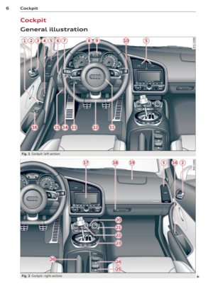 8
8 9
9 10
10 11
11 12
12 13
13 14
14 15
15 16
16 17
17 18
18 19
19 20
20 21
21 22
22 23
23 24
24 25
25 26
26 27
27 28
28 29
29 30
30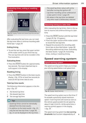 31
31 32
32 33
33 34
34 35
35 36
36 37
37 38
38 39
39 40
40 41
41 42
42 43
43 44
44 45
45 46
46 47
47 48
48 49
49 50
50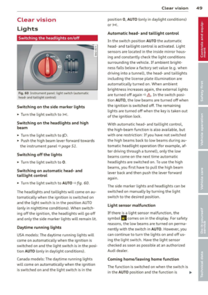 51
51 52
52 53
53 54
54 55
55 56
56 57
57 58
58 59
59 60
60 61
61 62
62 63
63 64
64 65
65 66
66 67
67 68
68 69
69 70
70 71
71 72
72 73
73 74
74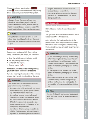 75
75 76
76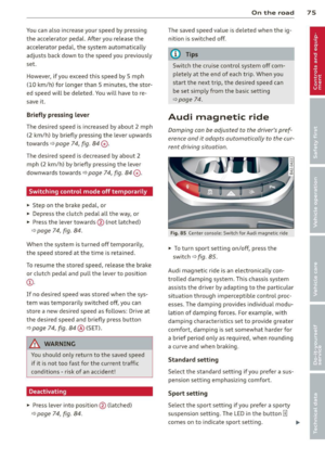 77
77 78
78 79
79 80
80 81
81 82
82 83
83 84
84 85
85 86
86 87
87 88
88 89
89 90
90 91
91 92
92 93
93 94
94 95
95 96
96 97
97 98
98 99
99 100
100 101
101 102
102 103
103 104
104 105
105 106
106 107
107 108
108 109
109 110
110 111
111 112
112 113
113 114
114 115
115 116
116 117
117 118
118 119
119 120
120 121
121 122
122 123
123 124
124 125
125 126
126 127
127 128
128 129
129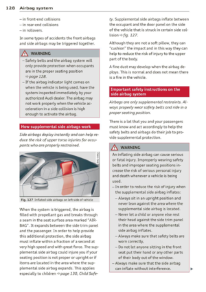 130
130 131
131 132
132 133
133 134
134 135
135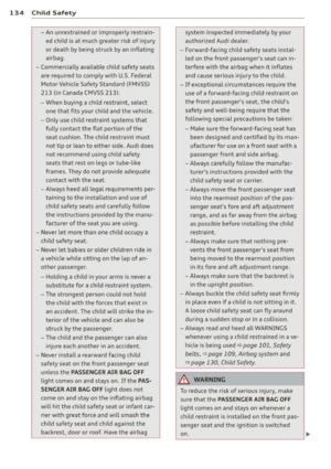 136
136 137
137 138
138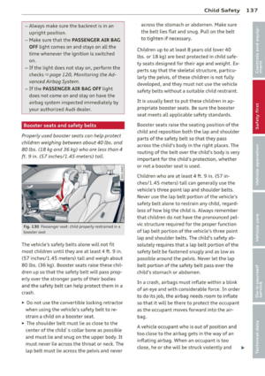 139
139 140
140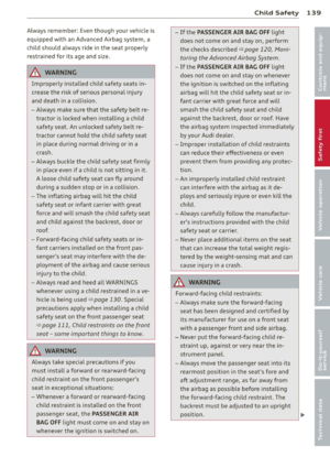 141
141 142
142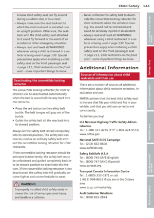 143
143 144
144 145
145 146
146 147
147 148
148 149
149 150
150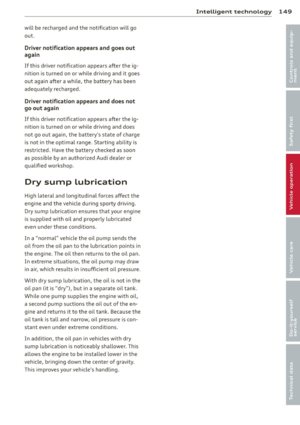 151
151 152
152 153
153 154
154 155
155 156
156 157
157 158
158 159
159 160
160 161
161 162
162 163
163 164
164 165
165 166
166 167
167 168
168 169
169 170
170 171
171 172
172 173
173 174
174 175
175 176
176 177
177 178
178 179
179 180
180 181
181 182
182 183
183 184
184 185
185 186
186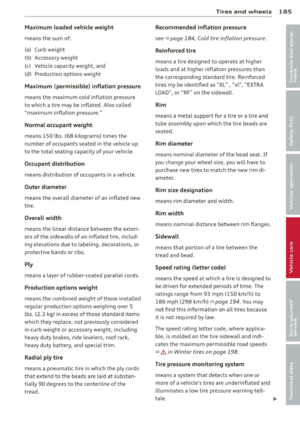 187
187 188
188 189
189 190
190 191
191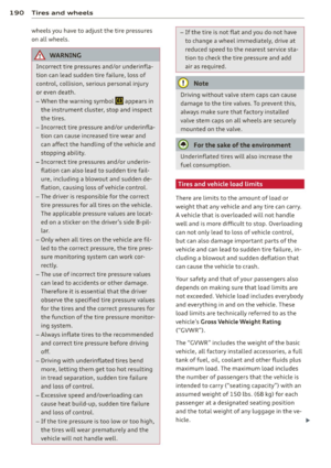 192
192 193
193 194
194 195
195 196
196 197
197 198
198 199
199 200
200 201
201 202
202 203
203 204
204 205
205 206
206 207
207 208
208 209
209 210
210 211
211 212
212 213
213 214
214 215
215 216
216 217
217 218
218 219
219 220
220 221
221 222
222 223
223 224
224 225
225 226
226 227
227 228
228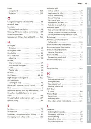 229
229 230
230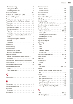 231
231 232
232 233
233 234
234 235
235