Page 57 of 94

PERIODIC MAINTENANCE AND ADJUSTMENT
6-11
2
3
4
5
67
8
9
EAU1985C
Engine oil and oil filter
cartridge
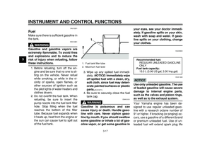
The engine oil level should be checked
before each ride. In addition, the oil
must be changed and the oil filter car-
tridge replaced at the intervals speci-
fied in the periodic maintenance and
lubrication chart.
To check the engine oil level
1. Place the vehicle on the center-
stand. A slight tilt to the side can
result in a false reading.
2. Start the engine, warm it up for two
minutes, and then turn it off.
NOTICE
ECA11290
The engine must be cold before pro-
ceeding with the oil level check, oth-
erwise the check will result in a false
reading.
3. Wait two minutes until the oil set-
tles, and then check the oil level
through the check window located
at the bottom-left side of the crank-
case.
TIP
The engine oil should be between the
minimum and maximum level marks.
4. If the engine oil is below the mini-
mum level mark, add sufficient oil
of the recommended type to raise
it to the correct level.
To change the engine oil (with or
without oil filter cartridge replace-
ment)
1. Place the vehicle on a level sur-
face.
2. Start the engine, warm it up forseveral minutes, and then turn it
off.
3. Place an oil pan under the engine
to collect the used oil.
4. Remove the engine oil filler cap,
the engine oil drain bolt and its
gasket to drain the oil from the
crankcase.
1. Engine oil level check window
2. Maximum level mark
3. Minimum level mark
1
32
1. Engine oil filler cap
1
Page 58 of 94
PERIODIC MAINTENANCE AND ADJUSTMENT
6-12
1
2
3
4
5
6
7
8
9
5. Check the O-ring for damage and
replace it if necessary.
TIP
Skip steps 6–8 if the oil filter cartridge is
not being replaced.
6. Remove the oil filter cartridge with
an oil filter wrench.
TIP
An oil filter wrench is available at a
Yamaha dealer.
7. Apply a thin coat of clean engine
oil to the O-ring of the new oil filter
cartridge.
1. Engine oil drain bolt
2. O-ring
3. Gasket
123
1. Engine oil drain bolt
2. O-ring
12
1. Oil filter wrench
2. Oil filter cartridge
2
1
Page 59 of 94

PERIODIC MAINTENANCE AND ADJUSTMENT
6-13
2
3
4
5
67
8
9
TIP
Make sure that the O-ring is properly
seated.
8. Install the new oil filter cartridge,
and then tighten it to the specified
torque with a torque wrench.9. Install the engine oil drain bolt and
its new gasket, and then tighten
the bolt to the specified torque.
10. Refill with the specified amount of
the recommended engine oil, and
then install and tighten the oil filler
cap.
TIP
Be sure to wipe off spilled oil on any
parts after the engine and exhaust sys-
tem have cooled down.
NOTICE
ECA11620
�
In order to prevent clutch slip-
page (since the engine oil also
lubricates the clutch), do not
mix any chemical additives. Do
not use oils with a diesel speci-
fication of “CD” or oils of a high-
er quality than specified. In
addition, do not use oils labeled
“ENERGY CONSERVING II” or
higher.
�
Make sure that no foreign mate-
rial enters the crankcase.
1. O-ring
1
1. Torque wrench
Tightening torque:
Oil filter cartridge:
17 Nm (1.7 m·kgf, 12.3 ft·lbf)
Tightening torque:
Engine oil drain bolt:
43 Nm (4.3 m·kgf, 31.1 ft·lbf)
1
Recommended engine oil:
See page 8-1.
Oil quantity:
Without oil filter cartridge replace-
ment:
2.80 L (2.96 US qt, 2.46 Imp.qt)
With oil filter cartridge replacement:
2.90 L (3.07 US qt, 2.55 Imp.qt)
Page 60 of 94

PERIODIC MAINTENANCE AND ADJUSTMENT
6-14
1
2
3
4
5
6
7
8
9
11. Start the engine, and then let it idle
for several minutes while checking
it for oil leakage. If oil is leaking, im-
mediately turn the engine off and
check for the cause.
12. Turn the engine off, and then
check the oil level and correct it if
necessary.
13. Reset the oil change indicator.
(See page 3-9.)
TIP
If the engine oil is changed before the
oil change indicator comes on (i.e. be-
fore the periodic oil change interval has
been reached), the indicator must be
reset after the oil change for the next
periodic oil change to be indicated at
the correct time.
EAU19997
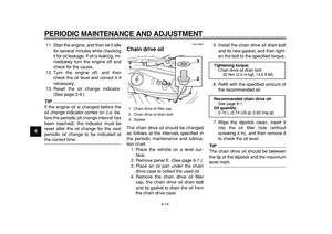
Chain drive oil
The chain drive oil should be changed
as follows at the intervals specified in
the periodic maintenance and lubrica-
tion chart.
1. Place the vehicle on a level sur-
face.
2. Remove panel E. (See page 6-7.)
3. Place an oil pan under the chain
drive case to collect the used oil.
4. Remove the chain drive oil filler
cap, the chain drive oil drain bolt
and its gasket to drain the oil from
the chain drive case.5. Install the chain drive oil drain bolt
and its new gasket, and then tight-
en the bolt to the specified torque.
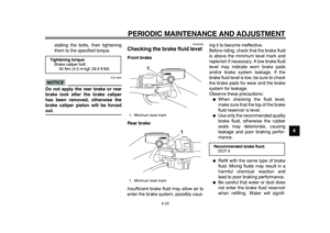
6. Refill with the specified amount of
the recommended oil.
7. Wipe the dipstick clean, insert it
into the oil filler hole (without
screwing it in), and then remove it
to check the oil level.
TIP
The chain drive oil should be between
the tip of the dipstick and the maximum
level mark.
1. Chain drive oil filler cap
2. Chain drive oil drain bolt
3. Gasket
1
23
Tightening torque:
Chain drive oil drain bolt:
20 Nm (2.0 m·kgf, 14.5 ft·lbf)
Recommended chain drive oil:
See page 8-1.
Oil quantity:
0.70 L (0.74 US qt, 0.62 Imp.qt)
Page 61 of 94

PERIODIC MAINTENANCE AND ADJUSTMENT
6-15
2
3
4
5
67
8
9
8. If the chain drive oil is not between
the tip of the dipstick and the max-
imum level mark, add sufficient oil
of the recommended type to raise
it to the correct level.
9. Insert the dipstick into the oil filler
hole, and then tighten the oil filler
cap.
NOTICE
ECA15010
�
Make sure that no foreign mate-
rial enters the chain drive case.
�
Make sure that no oil gets on the
tire or wheel.
10. Check the chain drive case for oil
leakage. If leakage is found, checkfor the cause.
11. Install the panel.
EAU20070
Coolant
The coolant level should be checked
before each ride. In addition, the cool-
ant must be changed at the intervals
specified in the periodic maintenance
and lubrication chart.
EAU46331
To check the coolant level
1. Place the vehicle on the center-
stand.
TIP
�
The coolant level must be checked
on a cold engine since the level
varies with engine temperature.
�
Make sure that the vehicle is posi-
tioned straight up when checking
the coolant level. A slight tilt to the
side can result in a false reading.
2. Check the coolant level through
the check window.
TIP
The coolant should be between the
minimum and maximum level marks.
1. Maximum level mark
2. Tip of the chain drive oil dipstick
1
2
Page 62 of 94

PERIODIC MAINTENANCE AND ADJUSTMENT
6-16
1
2
3
4
5
6
7
8
9
3. If the coolant is at or below the
minimum level mark, lift up the
right floorboard mat as shown.
4. Remove the coolant reservoir cov-er by removing the screw.
5. Open the coolant reservoir cap,
add coolant to the maximum level
mark, and then close the reservoir
cap.
WARNING! Remove only
the coolant reservoir cap. Never
attempt to remove the radiator
cap when the engine is
hot.
[EWA15161]
NOTICE:
If coolant is
not available, use distilled water
or soft tap water instead. Do not
use hard water or salt water
since it is harmful to the engine.
If water has been used instead
of coolant, replace it with cool-
ant as soon as possible, other-wise the cooling system will not
be protected against frost and
corrosion. If water has been
added to the coolant, have a
Yamaha dealer check the anti-
freeze content of the coolant as
soon as possible, otherwise the
effectiveness of the coolant will
be reduced.
[ECA10472]
6. Install the coolant reservoir cover
by installing the screw.
7. Place the right floorboard mat in
the original position.
1. Maximum level mark
2. Minimum level mark
3. Coolant level check window
1. Right floorboard mat
3
1
2
1
1. Coolant reservoir cover
2. Screw
12
1. Coolant reservoir cap
Coolant reservoir capacity (up to the
maximum level mark):
0.25 L (0.26 US qt, 0.22 Imp.qt)
1
Page 63 of 94

PERIODIC MAINTENANCE AND ADJUSTMENT
6-17
2
3
4
5
67
8
9
EAU45021
Replacing the air filter element
The air filter element should be re-
placed at the intervals specified in the
periodic maintenance and lubrication
chart. Replace the air filter element
more frequently if you are riding in un-
usually wet or dusty areas.
To replace the air filter element
1. Remove panels C and D. (See
page 6-7.)
2. Remove the air filter case cover by
removing the screws.
3. Pull the air filter element out.4. Insert a new air filter element into
the air filter case.
NOTICE:
Make
sure that the air filter element is
properly seated in the air filter
case. The engine should never
be operated without the air filter
element installed, otherwise the
piston(s) and/or cylinder(s) may
become excessively worn.
[ECA10481]
5. Install the air filter case cover by in-
stalling the screws.
6. Install the panels.
EAU33482
Adjusting the engine idling
speed
The engine idling speed must be
checked and, if necessary, adjusted as
follows at the intervals specified in the
periodic maintenance and lubrication
chart.
The engine should be warm before
making this adjustment.
1. Remove panel F. (See page 6-7.)
2. Check the engine idling speed
and, if necessary, adjust it to spec-
ification by turning the idle adjust-
ing screw. To increase the engine
idling speed, turn the screw in di-
rection (a). To decrease the en-
gine idling speed, turn the screw in
direction (b).
1. Screw
2. Air filter case cover
2
1
1
1. Air filter element
1
Page 64 of 94
PERIODIC MAINTENANCE AND ADJUSTMENT
6-18
1
2
3
4
5
6
7
8
9
TIP
If the specified idling speed cannot be
obtained as described above, have a
Yamaha dealer make the adjustment.
3. Install the panel.
EAU21384
Checking the throttle grip free
play
The throttle grip free play should mea-
sure 3.0–5.0 mm (0.12–0.20 in) at the
inner edge of the throttle grip. Periodi-
cally check the throttle grip free play
and, if necessary, have a Yamaha
dealer adjust it.
EAU21401
Valve clearance
The valve clearance changes with use,
resulting in improper air-fuel mixture
and/or engine noise. To prevent this
from occurring, the valve clearance
must be adjusted by a Yamaha dealer
at the intervals specified in the periodic
maintenance and lubrication chart.
1. Idle adjusting screw
Engine idling speed:
1100–1300 r/min
1(a) (b)
1. Throttle grip free play1