Page 49 of 94
PERIODIC MAINTENANCE AND ADJUSTMENT
6-3
2
3
4
5
67
8
9
EAU46861
TIP
�
The annual checks must be performed every year, except if a kilometer-based maintenance, or for the UK, a
mileage-based maintenance, is performed instead.
�
From 50000 km (30000 mi), repeat the maintenance intervals starting from 10000 km (6000 mi).
�
Items marked with an asterisk should be performed by a Yamaha dealer as they require special tools, data and technical
skills.
EAU46910
Periodic maintenance chart for the emission control system
NO. ITEM CHECK OR MAINTENANCE JOBODOMETER READING
ANNUAL
CHECK 1000 km
(600 mi)10000 km
(6000 mi)20000 km
(12000 mi)30000 km
(18000 mi)40000 km
(24000 mi)
1*
Fuel line
• Check fuel hoses for cracks or
damage.
√√√√√
2*
Spark plugs
• Check condition.
• Clean and regap.
√√
• Replace.
√√
3*
Valves
• Check valve clearance.
• Adjust.Every 40000 km (24000 mi)
4*
Fuel injection
• Adjust engine idling speed and
synchronization.
√√√√√√
Page 50 of 94
1")
PERIODIC MAINTENANCE AND ADJUSTMENT
6-4
1
2
3
4
5
6
7
8
9
EAU1770C
General maintenance and lubrication chart
NO. ITEM CHECK OR MAINTENANCE JOBODOMETER READING
ANNUAL
CHECK 1000 km
(600 mi)10000 km
(6000 mi)20000 km
(12000 mi)30000 km
(18000 mi)40000 km
(24000 mi)
1
Air filter element
• Replace.
√√
2*
V-belt case air filter
elements
• Clean.
√√
• Replace.
√√
3*
Front brake
• Check operation, fluid level and
vehicle for fluid leakage.
√√√√√√
• Replace brake pads. Whenever worn to the limit
4*
Rear brake
• Check operation, fluid level and
vehicle for fluid leakage.
√√√√√√
• Replace brake pads. Whenever worn to the limit
5*
Brake hoses
• Check for cracks or damage.
√√√√√
• Replace. Every 4 years
6
Rear brake lock
• Check operation.
• Adjust.
√√√√√√
7*
Wheels
• Check runout and for damage.
√√√√
8*
Tires
• Check tread depth and for
damage.
• Replace if necessary.
• Check air pressure.
• Correct if necessary.
√√√√√
9*
Wheel bearings
• Check bearing for looseness or
damage.
√√√√
10 *
Steering bearings
• Check bearing play and steering
for roughness.
√√√√√
• Lubricate with
lithium-soap-based grease.Every 20000 km (12000 mi)
Page 51 of 94

PERIODIC MAINTENANCE AND ADJUSTMENT
6-5
2
3
4
5
67
8
9
11 *
Chassis fasteners
• Make sure that all nuts, bolts
and screws are properly
tightened.
√√√√√
12
Front brake lever
pivot shaft
• Lubricate with silicone grease.
√√√√√
13
Rear brake lever
pivot shaft
• Lubricate with silicone grease.
√√√√√
14
Sidestand,
centerstand
• Check operation.
• Lubricate with
lithium-soap-based grease.
√√√√√
15 *
Sidestand switch
• Check operation.
√√√√√√
16 *
Front fork
• Check operation and for oil
leakage.
√√√√
17 *
Shock absorber
assembly
• Check operation and shock
absorber for oil leakage.
√√√√
18
Engine oil
• Change. (See pages 3-9 and
6-11.)
√
When the oil change indicator flashes
• Check oil level and vehicle for oil
leakage.Every 5000 km (3000 mi)
√
19
Engine oil filter
cartridge
• Replace.
√√√
20 *
Cooling system
• Check coolant level and vehicle
for coolant leakage.
√√√√√
• Change. Every 3 years
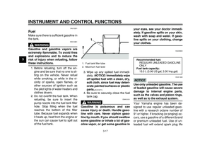
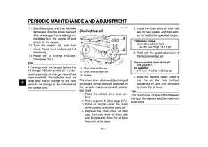
21
Chain drive oil
• Check vehicle for oil leakage.
• Change.
√√√√
22 *
V-belt
• Replace. When the V-belt replacement indicator flashes [every 20000 km (12000 mi)]
23 *
Front and rear brake
switches
• Check operation.
√√√√√√
NO. ITEM CHECK OR MAINTENANCE JOBODOMETER READING
ANNUAL
CHECK 1000 km
(600 mi)10000 km
(6000 mi)20000 km
(12000 mi)30000 km
(18000 mi)40000 km
(24000 mi)
Page 52 of 94

PERIODIC MAINTENANCE AND ADJUSTMENT
6-6
1
2
3
4
5
6
7
8
9
EAU38262
TIP
�
Engine air filter and V-belt air filters
• This model’s engine air filter is equipped with a disposable oil-coated paper element, which must not be cleaned with
compressed air to avoid damaging it.
• The engine air filter element needs to be replaced and the V-belt air filter elements need to be serviced more frequent-
ly when riding in unusually wet or dusty areas.
�
Hydraulic brake service
• After disassembling the brake master cylinders and calipers, always change the fluid. Regularly check the brake fluid
levels and fill the reservoirs as required.
• Every two years replace the internal components of the brake master cylinders and calipers, and change the brake
fluid.
• Replace the brake hoses every four years and if cracked or damaged.
24
Moving parts and
cables
• Lubricate.
√√√√√
25 *
Throttle grip
• Check operation.
• Check throttle grip free play, and
adjust if necessary.
• Lubricate cable and grip
housing.
√√√√√
26 *
Lights, signals and
switches
• Check operation.
• Adjust headlight beam.
√√√√√√
NO. ITEM CHECK OR MAINTENANCE JOBODOMETER READING
ANNUAL
CHECK 1000 km
(600 mi)10000 km
(6000 mi)20000 km
(12000 mi)30000 km
(18000 mi)40000 km
(24000 mi)
Page 53 of 94
PERIODIC MAINTENANCE AND ADJUSTMENT
6-7
2
3
4
5
67
8
9
EAU18771
Removing and installing
panels
The panels shown need to be removed
to perform some of the maintenance
jobs described in this chapter. Refer to
this section each time a panel needs to
be removed and installed.
EAU45013
Panel A
To remove the panel
1. Remove the quick fasteners.2. Remove the panel by pulling its
upper left and right sides to un-
hook them, then pulling the panel
downward as shown.
To install the panel
Place the panel in the original position,
and then install the quick fasteners.
1. Panel A
2. Panel B
3. Panel C
4. Panel D
5. Panel E
34
5
12
1. Panel F
1. Panel A
2. Quick fastener
1
2
1
1. Panel A
1
Page 54 of 94
PERIODIC MAINTENANCE AND ADJUSTMENT
6-8
1
2
3
4
5
6
7
8
9Panel B
To remove the panel
1. Remove panel A.
2. Pull the rear view mirror rubber
cover on each mirror upward, and
then remove the rear view mirrors
by removing the nuts.
3. Remove the screws, and then pull
the panel outward.To install the panel
1. Place the panel in the original po-
sition, and then install the screws.
2. Install the rear view mirrors by in-
stalling the nuts, and then place
the rubber cover on each mirror in
the original position.
3. Install panel A.
Panel C
To remove the panelRemove the screws, and then pull the
panel upward.To install the panel
Place the panel in the original position,
and then install the screws.
Panel D
To remove the panel1. Remove panel C.
2. Remove the screws, and then pull
the panel backward and upward.
1. Nut
2. Rubber cover
3. Rear view mirror
1
32
1. Screw
2. Panel B
21
1
1. Screw
2. Panel C
2
1
Page 55 of 94
PERIODIC MAINTENANCE AND ADJUSTMENT
6-9
2
3
4
5
67
8
9
To install the panel
1. Place the panel in the original po-
sition, and then install the screws.
2. Install panel C.
Panel E
To remove the panelRemove the screws, and then pull the
panel outward.To install the panel
Place the panel in the original position,
and then install the screws.
Panel F
To remove the panelRemove the screws, and then pull the
panel outward.To install the panel
Place the panel in the original position,
and then install the screws.
1. Screw
2. Panel D
2
1
1. Screw
1
1. Screw
1
1
Page 56 of 94

PERIODIC MAINTENANCE AND ADJUSTMENT
6-10
1
2
3
4
5
6
7
8
9
EAU19642
Checking the spark plugs
The spark plugs are important engine
components, which should be checked
periodically, preferably by a Yamaha
dealer. Since heat and deposits will
cause any spark plug to slowly erode,
they should be removed and checked
in accordance with the periodic mainte-
nance and lubrication chart. In addition,
the condition of the spark plugs can re-
veal the condition of the engine.
The porcelain insulator around the cen-
ter electrode of each spark plug should
be a medium-to-light tan (the ideal color
when the vehicle is ridden normally),
and all spark plugs installed in the en-
gine should have the same color. If any
spark plug shows a distinctly different
color, the engine could be operating im-
properly. Do not attempt to diagnose
such problems yourself. Instead, have
a Yamaha dealer check the vehicle.
If a spark plug shows signs of electrode
erosion and excessive carbon or other
deposits, it should be replaced.Before installing a spark plug, the spark
plug gap should be measured with a
wire thickness gauge and, if necessary,
adjusted to specification.
Clean the surface of the spark plug
gasket and its mating surface, and then
wipe off any grime from the spark plug
threads.
TIP
If a torque wrench is not available when
installing a spark plug, a good estimate
of the correct torque is 1/4–1/2 turn
past finger tight. However, the spark
plug should be tightened to the speci-
fied torque as soon as possible.
Specified spark plug:
NGK/CR7E
1. Spark plug gap
Spark plug gap:
0.7–0.8 mm (0.028–0.031 in)
Tightening torque:
Spark plug:
13 Nm (1.3 m·kgf, 9.4 ft·lbf)