Page 25 of 94
, the
indicator “V-BELT")
INSTRUMENT AND CONTROL FUNCTIONS
3-10
2
34
5
6
7
8
9
V-belt replacement indicator “V-BELT”
flashes (i.e. before the periodic V-belt
change interval has been reached), the
indicator “V-BELT” must be reset after
the V-belt change for the next periodic
V-belt change to be indicated at the
correct time.
The electrical circuit of the indicator can
be checked according to the following
procedure.
1. Turn the key to “ON” and make
sure that the engine stop switch is
set to “ ”.
2. Check that the V-belt replacement
indicator comes on for a few sec-
onds and then goes off.
3. If the V-belt replacement indicator
does not come on, have a Yamaha
dealer check the electrical circuit.
Self-diagnosis device
This model is equipped with a self-diag-
nosis device for various electrical cir-
cuits.
If a problem is detected in any of those
circuits, the engine trouble warning light
comes on and the display indicates an
error code.
If the display indicates any error codes,
note the code number, and then have a
Yamaha dealer check the vehicle.
The self-diagnosis device also detects
problems in the immobilizer system cir-
cuits.
If a problem is detected in any of the im-
mobilizer system circuits, the immobi-
lizer system indicator light flashes andthe display indicates an error code.
TIP
If the display indicates error code 52,
this could be caused by transponder in-
terference. If this error code appears,
try the following.
1. Use the code re-registering key to
start the engine.
TIP
Make sure there are no other immobi-
lizer keys close to the main switch, and
do not keep more than one immobilizer
key on the same key ring! Immobilizer
system keys may cause signal interfer-
ence, which may prevent the engine
from starting.
2. If the engine starts, turn it off and
try starting the engine with the
standard keys.
3. If one or both of the standard keys
do not start the engine, take the
vehicle, the code re-registering
key and both standard keys to a
Yamaha dealer and have the stan-
dard keys re-registered.
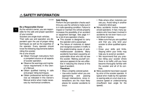
1. Error code display
1
Page 26 of 94
INSTRUMENT AND CONTROL FUNCTIONS
3-11
1
2
3
4
5
6
7
8
9
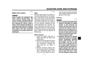
NOTICE
ECA11590
If the display indicates an error
code, the vehicle should be checked
as soon as possible in order to avoid
engine damage.
EAU12331
Anti-theft alarm (optional)
This model can be equipped with an
optional anti-theft alarm by a Yamaha
dealer. Contact a Yamaha dealer for
more information.
EAU12348
Handlebar switches
Left
1. Pass switch “PASS”
2. Dimmer switch “ / ”
3. Turn signal switch “ / ”
4. Horn switch “ ”
1
2
3
4
Page 27 of 94

INSTRUMENT AND CONTROL FUNCTIONS
3-12
2
34
5
6
7
8
9 Right
EAU12360
Pass switch “PASS”
Press this switch to flash the headlight.
EAU12400
Dimmer switch “/”
Set this switch to “ ” for the high
beam and to “ ” for the low beam.
EAU12460
Turn signal switch “/”
To signal a right-hand turn, push this
switch to “ ”. To signal a left-hand
turn, push this switch to “ ”. When re-
leased, the switch returns to the centerposition. To cancel the turn signal
lights, push the switch in after it has re-
turned to the center position.
EAU12500
Horn switch “”
Press this switch to sound the horn.
EAU12660
Engine stop switch “/”
Set this switch to “ ” before starting
the engine. Set this switch to “ ” to
stop the engine in case of an emergen-
cy, such as when the vehicle overturns
or when the throttle cable is stuck.
EAU12721
Start switch “”
With the sidestand up, push this switch
while applying the front or rear brake to
crank the engine with the starter. See
page 5-1 for starting instructions prior
to starting the engine.
EAU44710
The engine trouble warning light and
ABS warning light (ABS model only)
will come on when the key is turned to
“ON” and the start switch is pushed, butthis does not indicate a malfunction.
EAU12733
Hazard switch “”
With the key in the “ON” or “ ” posi-
tion, use this switch to turn on the haz-
ard lights (simultaneous flashing of all
turn signal lights).
The hazard lights are used in case of
an emergency or to warn other drivers
when your vehicle is stopped where it
might be a traffic hazard.
NOTICE
ECA10061
Do not use the hazard lights for an
extended length of time with the en-
gine not running, otherwise the bat-
tery may discharge.
1. Engine stop switch “ / ”
2. Hazard switch “ ”
3. Start switch “ ”
1
23
Page 28 of 94

INSTRUMENT AND CONTROL FUNCTIONS
3-13
1
2
3
4
5
6
7
8
9
EAU44910
Front brake lever
The front brake lever is located at the
right handlebar grip. To apply the front
brake, pull this lever toward the handle-
bar grip.
The front brake lever is equipped with a
position adjusting dial. To adjust the
distance between the front brake lever
and the handlebar grip, turn the adjust-
ing dial while holding the front brake le-
ver pushed away from the handlebar
grip. Make sure that the appropriate
setting on the adjusting dial is alignedwith the “ ” mark on the front brake le-
ver.
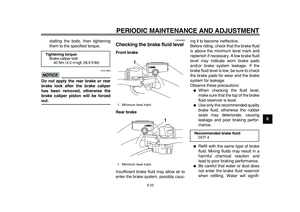
EAU44921
Rear brake lever
The rear brake lever is located at the
left handlebar grip. To apply the rear
brake, pull this lever toward the handle-
bar grip.
The rear brake lever is equipped with a
position adjusting dial. To adjust the
distance between the rear brake lever
and the handlebar grip, turn the adjust-
ing dial while holding the rear brake le-
ver pushed away from the handlebar
grip. Make sure that the appropriate
setting on the adjusting dial is aligned
1. Front brake lever
2. Brake lever position adjusting dial
3. “ ” mark
4. Distance between brake lever and
handlebar grip
1
3
4 2
1. Rear brake lever
2. Brake lever position adjusting dial
3. “ ” mark
4. Distance between brake lever and
handlebar grip
1
3
42
Page 29 of 94
INSTRUMENT AND CONTROL FUNCTIONS
3-14
2
34
5
6
7
8
9
with the “ ” mark on the rear brake le-
ver.
EAU12962
Rear brake lock lever
This vehicle is equipped with a rear
brake lock lever to prevent the rear
wheel from moving while stopped at
traffic signals, railroad crossings, etc.
To lock the rear wheel
Push the rear brake lock lever to the left
until it snaps into place.
To unlock the rear wheel
Push the rear brake lock lever back to
the original position.
TIP
�
Be sure to check that the rear
wheel does not move when therear brake lock lever is applied.
�
To provide secure locking of the
rear wheel, apply the rear brake le-
ver first before moving the rear
brake lock lever to the left.
WARNING
EWA12361
Never move the rear brake lock lever
to the left while the vehicle is mov-
ing, otherwise loss of control or an
accident may result. Make sure that
the vehicle is stopped before mov-
ing the rear brake lock lever to the
left.
1. Rear brake lock lever
1
Page 30 of 94

The Yamaha ABS (Anti-lock Brake
System) features a dual electronic con-
trol system, which acts on the fr")
INSTRUMENT AND CONTROL FUNCTIONS
3-15
1
2
3
4
5
6
7
8
9
EAU12995
ABS (for ABS models)
The Yamaha ABS (Anti-lock Brake
System) features a dual electronic con-
trol system, which acts on the front and
rear brakes independently. The ABS
securely controls wheel lockup during
emergency braking on changing road
surfaces and under various weather
conditions, thereby maximizing tire ad-
hesion and performance while provid-
ing a smooth braking action. The ABS
is monitored by an ECU, which will
have recourse to manual braking if a
malfunction occurs.
WARNING
EWA10090
�
The ABS performs best on long
braking distances.
�
On certain (rough or gravel)
roads, the braking distance may
be longer with than without the
ABS. Therefore, always keep a
sufficient distance to the vehi-
cle ahead to match the riding
speed.
TIP
�
The ABS performs a self-diagno-sis test for a few seconds each
time the vehicle first starts off after
the key was turned to “ON”. During
this test, a “clicking” noise can be
heard from the front of the vehicle,
and if either brake lever is even
slightly applied, a vibration can be
felt at the lever, but these do not in-
dicate a malfunction.
�
When the ABS is activated, the
brakes are operated in the usual
way. A pulsating action may be felt
at the brake levers, but this does
not indicate a malfunction.
�
This ABS has a test mode which
allows the owner to experience the
pulsating at the brake levers when
the ABS is operating. However,
special tools are required, so
please consult your Yamaha deal-
er when performing this test.
NOTICE
ECA16120
Keep any type of magnets (including
magnetic pick-up tools, magnetic
screwdrivers, etc.) away from the
front and rear wheel hubs, otherwise
the magnetic rotors equipped in thewheel hubs may be damaged, result-
ing in improper performance of the
ABS system.
1. Front wheel hub
1. Rear wheel hub
11
Page 31 of 94
INSTRUMENT AND CONTROL FUNCTIONS
3-16
2
34
5
6
7
8
9
EAU13175
Fuel tank cap
To remove the fuel tank cap
1. Open the lid by pulling the lever up.
2. Insert the key into the lock and turn
it clockwise. The lock will be re-
leased and the fuel tank cap can
be removed.
To install the fuel tank cap
1. Align the match marks, insert the
fuel tank cap into the tank opening,
and then push down on the cap.
2. Turn the key counterclockwise tothe original position, and then re-
move it.
3. Close the lid.
WARNING
EWA11261
Make sure that the fuel tank cap is
properly installed and locked in
place before riding the scooter.
Leaking fuel is a fire hazard.
1. Opening lever
2. Lid
1
2
1. Fuel tank cap
1. Match marks
1
1
Page 32 of 94

INSTRUMENT AND CONTROL FUNCTIONS
3-17
1
2
3
4
5
6
7
8
9
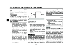
EAU13221
Fuel
Make sure there is sufficient gasoline in
the tank.
WARNING
EWA10881
Gasoline and gasoline vapors are
extremely flammable. To avoid fires
and explosions and to reduce the
risk of injury when refueling, follow
these instructions.
1. Before refueling, turn off the en-
gine and be sure that no one is sit-
ting on the vehicle. Never refuel
while smoking, or while in the vi-
cinity of sparks, open flames, or
other sources of ignition such as
the pilot lights of water heaters and
clothes dryers.
2. Do not overfill the fuel tank. When
refueling, be sure to insert the
pump nozzle into the fuel tank filler
hole. Stop filling when the fuel
reaches the bottom of the filler
tube. Because fuel expands when
it heats up, heat from the engine or
the sun can cause fuel to spill out
of the fuel tank.3. Wipe up any spilled fuel immedi-
ately.
NOTICE:
Immediately wipe
off spilled fuel with a clean, dry,
soft cloth, since fuel may deteri-
orate painted surfaces or plastic
parts.
[ECA10071]
4. Be sure to securely close the fuel
tank cap.
WARNING
EWA15151
Gasoline is poisonous and can
cause injury or death. Handle gaso-
line with care. Never siphon gaso-
line by mouth. If you should swallow
some gasoline or inhale a lot of gas-
oline vapor, or get some gasoline inyour eyes, see your doctor immedi-
ately. If gasoline spills on your skin,
wash with soap and water. If gaso-
line spills on your clothing, change
your clothes.
EAU33520
NOTICE
ECA11400
Use only unleaded gasoline. The use
of leaded gasoline will cause severe
damage to internal engine parts,
such as the valves and piston rings,
as well as to the exhaust system.
Your Yamaha engine has been de-
signed to use regular unleaded gaso-
line with a research octane number of
91 or higher. If knocking (or pinging) oc-
curs, use a gasoline of a different brand
or premium unleaded fuel. Use of un-
leaded fuel will extend spark plug life
1. Fuel tank filler tube
2. Maximum fuel level
21
Recommended fuel:
REGULAR UNLEADED GASOLINE
ONLY
Fuel tank capacity:
15.0 L (3.96 US gal, 3.30 Imp.gal)