Page 73 of 94

PERIODIC MAINTENANCE AND ADJUSTMENT
6-27
2
3
4
5
67
8
9
EAU45511
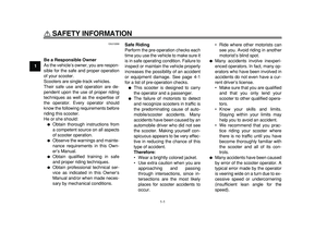
Checking the steering
Worn or loose steering bearings may
cause danger. Therefore, the operation
of the steering must be checked as fol-
lows at the intervals specified in the pe-
riodic maintenance and lubrication
chart.
1. Place the vehicle on the center-
stand.
WARNING! To avoid inju-
ry, securely support the vehicle
so there is no danger of it falling
over.
[EWA10751]
2. Hold the lower ends of the front
fork legs and try to move them for-
ward and backward. If any free
play can be felt, have a Yamaha
dealer check or repair the steering.
EAU23291
Checking the wheel bearings
The front and rear wheel bearings must
be checked at the intervals specified in
the periodic maintenance and lubrica-
tion chart. If there is play in the wheel
hub or if the wheel does not turn
smoothly, have a Yamaha dealer check
the wheel bearings.
EAU45034
Battery
The battery is located under panel B.
(See page 6-7.)
This model is equipped with a VRLA
(Valve Regulated Lead Acid) battery.
There is no need to check the electro-
lyte or to add distilled water. However,
the battery lead connections need to be
checked and, if necessary, tightened.
WARNING
EWA10760
�
Electrolyte is poisonous and
dangerous since it contains sul-
furic acid, which causes severe
burns. Avoid any contact with
skin, eyes or clothing and al-
ways shield your eyes when
working near batteries. In case
of contact, administer the fol-
lowing FIRST AID.
•EXTERNAL: Flush with plenty
of water.
•INTERNAL: Drink large quan-
tities of water or milk and im-
mediately call a physician.
•EYES: Flush with water for 15
minutes and seek prompt
medical attention.
Page 74 of 94

PERIODIC MAINTENANCE AND ADJUSTMENT
6-28
1
2
3
4
5
6
7
8
9
�
Batteries produce explosive hy-
drogen gas. Therefore, keep
sparks, flames, cigarettes, etc.,
away from the battery and pro-
vide sufficient ventilation when
charging it in an enclosed
space.
�
KEEP THIS AND ALL BATTER-
IES OUT OF THE REACH OF
CHILDREN.
To access the battery
1. Remove panel B. (See page 6-7.)
2. Remove the rubber cover shown
by removing the quick fasteners.
To charge the battery
Have a Yamaha dealer charge the bat-
tery as soon as possible if it seems to
have discharged. Keep in mind that the
battery tends to discharge more quickly
if the vehicle is equipped with optional
electrical accessories.
NOTICE
ECA16521
To charge a VRLA (Valve Regulated
Lead Acid) battery, a special (con-
stant-voltage) battery charger is re-
quired. Using a conventional battery
charger will damage the battery.To store the battery
1. If the vehicle will not be used for
more than one month, remove the
battery, fully charge it, and then
place it in a cool, dry place.
NOTICE:
When removing the
battery, be sure the key is
turned to “OFF”, then discon-
nect the negative lead before
disconnecting the positive
lead.
[ECA16302]
2. If the battery will be stored for more
than two months, check it at least
once a month and fully charge it if
necessary.
3. Fully charge the battery before in-
stallation.
4. After installation, make sure that
the battery leads are properly con-
nected to the battery terminals.
NOTICE
ECA16530
Always keep the battery charged.
Storing a discharged battery can
cause permanent battery damage.
1. Quick fastener
2. Rubber cover
21
1
1. Battery
2. Positive battery lead (red)
3. Negative battery lead (black)
1
2
3
Page 75 of 94
PERIODIC MAINTENANCE AND ADJUSTMENT
6-29
2
3
4
5
67
8
9
EAU46310
Replacing the fuses
The main fuse and the fuse box, which
contains the fuses for the individual cir-
cuits, are located under panel B. (See
page 6-7.)
1. Remove panel B. (See page 6-7.)
2. Remove the rubber cover shown
by removing the quick fasteners.
If a fuse is blown, replace it as follows.
1. Turn the key to “OFF” and turn off
the electrical circuit in question.
2. Remove the blown fuse, and then
install a new fuse of the specified
amperage.
WARNING! Do not
use a fuse of a higher amperagerating than recommended to
avoid causing extensive dam-
age to the electrical system and
possibly a fire.
[EWA15131]
For XP500For XP500A
For XP500
1. Quick fastener
2. Rubber cover
21
1
1. Main fuse
2. Spare main fuse
1
2
1. Main fuse
2. Spare main fuse
1. Fuse box
1
21
Page 76 of 94
PERIODIC MAINTENANCE AND ADJUSTMENT
6-30
1
2
3
4
5
6
7
8
9For XP500A For XP500 For XP500A
1. Fuse box
2. ABS solenoid fuse
3. ABS motor fuse
1
3
2
1. Headlight fuse
2. Ignition fuse
3. Backup fuse (for clock and rear storage
compartment light)
4. Radiator fan fuse
5. Fuel injection system fuse
6. Signaling system fuse
7. Spare fuse
8. Parking lighting fuse
7
7 7 8
123456
1. Headlight fuse
2. Ignition fuse
3. Backup fuse (for clock and rear storage
compartment light)
4. Radiator fan fuse
5. Fuel injection system fuse
6. Signaling system fuse
7. Spare fuse
8. ABS control unit fuse
9. Parking lighting fuse
10.Spare fuse
7
7 7 9
1
810
23456
Page 77 of 94

PERIODIC MAINTENANCE AND ADJUSTMENT
6-31
2
3
4
5
67
8
9
3. Turn the key to “ON” and turn on
the electrical circuit in question to
check if the device operates.
4. If the fuse immediately blows
again, have a Yamaha dealer
check the electrical system.
EAU23764
Replacing the headlight bulb
This model is equipped with a halogen
bulb headlight. If the headlight bulb
burns out, replace it as follows.
NOTICE
ECA10650
Take care not to damage the follow-
ing parts:
�
Headlight bulb
Do not touch the glass part of
the headlight bulb to keep it free
from oil, otherwise the transpar-
ency of the glass, the luminosity
of the bulb, and the bulb life will
be adversely affected. Thor-
oughly clean off any dirt and fin-
gerprints on the headlight bulb
using a cloth moistened with al-
cohol or thinner.
�
Headlight lens
Do not affix any type of tinted
film or stickers to the headlight
lens.
Do not use a headlight bulb of a
wattage higher than specified.
1. Disconnect the headlight coupler,
and then remove the headlight
bulb cover.
2. Unhook the headlight bulb holder,
and then remove the burnt-out bulb.
Specified fuses:
Main fuse:
30.0 A
Headlight fuse:
20.0 A
Signaling system fuse:
15.0 A
Ignition fuse:
10.0 A
Parking lighting fuse:
10.0 A
Radiator fan fuse:
15.0 A
Fuel injection system fuse:
10.0 A
ABS control unit fuse:
XP500A 5.0 A
ABS motor fuse:
XP500A 30.0 A
ABS solenoid fuse:
XP500A 20.0 A
Backup fuse:
10.0 A
1. Do not touch the glass part of the bulb.
1. Headlight coupler
2. Headlight bulb cover
1
2
Page 78 of 94
PERIODIC MAINTENANCE AND ADJUSTMENT
6-32
1
2
3
4
5
6
7
8
9
3. Place a new headlight bulb into po-
sition, and then secure it with the
bulb holder.
4. Install the headlight bulb cover,
and then connect the coupler.
5. Have a Yamaha dealer adjust the
headlight beam if necessary.
EAU43040
Tail/brake light
If the tail/brake light does not come on,
have a Yamaha dealer check its electri-
cal circuit or replace the bulb.
EAU43051
Replacing a front turn signal
light bulb
1. Place the scooter on the center-
stand.
2. Remove the socket (together with
the bulb) by turning it counter-
clockwise.
3. Remove the burnt-out bulb by pull-
ing it out.
4. Insert a new bulb into the socket.
5. Install the socket (together with the
bulb) by turning it clockwise.
1. Headlight bulb holder
2. Unhook.
1
2
1. Turn signal light bulb socket
1
Page 79 of 94
PERIODIC MAINTENANCE AND ADJUSTMENT
6-33
2
3
4
5
67
8
9
EAUT1330
Rear turn signal light bulb
If a rear turn signal light does not come
on, have a Yamaha dealer check the
electrical circuit or replace the bulb.
EAU24313
Replacing the license plate
light bulb
1. Remove the license plate light unit
by removing the screws.
2. Remove the license plate light bulb
socket (together with the bulb) by
pulling it out.3. Remove the burnt-out bulb by pull-
ing it out.
4. Insert a new bulb into the socket.
5. Install the socket (together with the
bulb) by pushing it in.
6. Install the license plate light unit by
installing the screws.
1. Screw
1
1. License plate light unit
2. License plate light bulb socket
12
Page 80 of 94

PERIODIC MAINTENANCE AND ADJUSTMENT
6-34
1
2
3
4
5
6
7
8
9
EAU43233
Replacing an auxiliary light
bulb
This model is equipped with two auxil-
iary lights. If an auxiliary light bulb burns
out, replace it as follows.
1. Remove the auxiliary light bulb
socket (together with the bulb) by
pulling it out.
2. Remove the burnt-out bulb by pull-
ing it out.
3. Insert a new bulb into the socket.
4. Install the socket (together with the
bulb) by pushing it in.
EAU25881
Troubleshooting
Although Yamaha scooters receive a
thorough inspection before shipment
from the factory, trouble may occur dur-
ing operation. Any problem in the fuel,
compression, or ignition systems, for
example, can cause poor starting and
loss of power.
The following troubleshooting charts
represent quick and easy procedures
for checking these vital systems your-
self. However, should your scooter re-
quire any repair, take it to a Yamaha
dealer, whose skilled technicians have
the necessary tools, experience, and
know-how to service the scooter prop-
erly.
Use only genuine Yamaha replace-
ment parts. Imitation parts may look like
Yamaha parts, but they are often inferi-
or, have a shorter service life and can
lead to expensive repair bills.
WARNING
EWA15141
When checking the fuel system, do
not smoke, and make sure there are
no open flames or sparks in the ar-
ea, including pilot lights from waterheaters or furnaces. Gasoline or
gasoline vapors can ignite or ex-
plode, causing severe injury or
property damage.
1. Auxiliary light bulb socket
1