Page 17 of 94

INSTRUMENT AND CONTROL FUNCTIONS
3-2
2
34
5
6
7
8
9 as they may cause signal inter-
ference.
EAU10472
Main switch/steering lock
The main switch/steering lock controls
the ignition and lighting systems, and is
used to lock the steering. The various
positions are described below.
TIP
Be sure to use the standard key (black
bow) for regular use of the vehicle. To
minimize the risk of losing the code
re-registering key (red bow), keep it in a
safe place and only use it for code
re-registering.
EAU34121
ON
All electrical circuits are supplied with
power; the meter lighting, taillight, li-cense plate light and auxiliary lights
come on, and the engine can be start-
ed. The key cannot be removed.
TIP
The headlights come on automatically
when the engine is started and stay on
until the key is turned to “OFF” or the
sidestand is moved down.
EAU10661
OFF
All electrical systems are off. The key
can be removed.
WARNING
EWA10061
Never turn the key to “OFF” or
“LOCK” while the vehicle is moving.
Otherwise the electrical systems will
be switched off, which may result in
loss of control or an accident.
EAU10683
LOCK
The steering is locked, and all electrical
systems are off. The key can be re-
moved.
Page 18 of 94

INSTRUMENT AND CONTROL FUNCTIONS
3-3
1
2
3
4
5
6
7
8
9
To lock the steering
1. Turn the handlebars all the way to
the left.
2. Push the key in from the “OFF” po-
sition, and then turn it to “LOCK”
while still pushing it.
3. Remove the key.
To unlock the steeringPush the key in, and then turn it to
“OFF” while still pushing it.
EAU10941
(Parking)
The steering is locked, and the taillight,
license plate light and auxiliary lights
are on. The hazard lights and turn sig-
nal lights can be turned on, but all other
electrical systems are off. The key can
be removed.
The steering must be locked before the
key can be turned to “ ”.
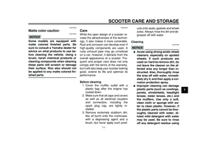
NOTICE
ECA11020
Do not use the parking position for
an extended length of time, other-
wise the battery may discharge.
EAU11004
Indicator and warning lights
EAU11030
Turn signal indicator lights “” and
“”
The corresponding indicator light flash-
es when the turn signal switch is
pushed to the left or right.
EAU11080
High beam indicator light “”
This indicator light comes on when thehigh beam of the headlight is switched
on.
EAU43023
Engine trouble warning light “”
This warning light comes on if an elec-
trical circuit monitoring the engine is not
working correctly. If this occurs, have a
Yamaha dealer check the self-diagno-
sis system.
The electrical circuit of the warning light
can be checked by turning the key to
“ON”. The warning light should come
on for a few seconds, and then go off.
If the warning light does not come on
initially when the key is turned to “ON”,
or if the warning light remains on, have
a Yamaha dealer check the electrical
circuit.
TIP
This warning light will come on when
the key is turned to “ON” and the start
switch is pushed, but this does not indi-
cate a malfunction.
1. Turn signal indicator lights “ ” and “ ”
2. High beam indicator light “ ”
3. Anti-lock Brake System (ABS) warning
light “ ” (for ABS models)
4. Immobilizer system indicator light
5. Engine trouble warning light “ ”
1
3
1
2
4
5
ABS
Page 19 of 94

NOTICE
ECA10831
If the ABS warning light comes on or
flashes while riding, the ABS m")
INSTRUMENT AND CONTROL FUNCTIONS
3-4
2
34
5
6
7
8
9
EAU43032
ABS warning light “” (for ABS
models)
NOTICE
ECA10831
If the ABS warning light comes on or
flashes while riding, the ABS may
not work correctly. If this occurs,
have a Yamaha dealer check the
electrical circuit.
See page 3-15 for an explanation of the
ABS.
The electrical circuit of the warning light
can be checked by setting the engine
stop switch to “ ” and turning the key
to “ON”. The warning light should come
on for a few seconds, and then go off.
If the warning light does not come on
initially when the key is turned to “ON”,
or if the warning light remains on, have
a Yamaha dealer check the electrical
circuit.
WARNING
EWA11350
When the ABS warning light comes
on or flashes while riding, the brake
system reverts to conventional brak-
ing. Therefore, be careful not tocause the wheel to lock during emer-
gency braking.
TIP
The ABS warning light may come on
while accelerating the engine with the
scooter on its centerstand, but this
does not indicate a malfunction.
EAU38624
Immobilizer system indicator light
The electrical circuit of the indicator
light can be checked by turning the key
to “ON”. The indicator light should
come on for a few seconds, and then
go off.
If the indicator light does not come on
initially when the key is turned to “ON”,
or if the indicator light remains on, have
a Yamaha dealer check the electrical
circuit.
When the key is turned to “OFF” and 30
seconds have passed, the indicator
light will start flashing indicating the im-
mobilizer system is enabled. After 24
hours have passed, the indicator light
will stop flashing, however the immobi-
lizer system is still enabled.
The self-diagnosis device also detectsproblems in the immobilizer system cir-
cuits. (See page 3-10 for an explana-
tion of the self-diagnosis device.)
ABS
Page 20 of 94
INSTRUMENT AND CONTROL FUNCTIONS
3-5
1
2
3
4
5
6
7
8
9
EAU11601
Speedometer
The speedometer shows the riding
speed.
When the key is turned to “ON”, the
speedometer needle will sweep once
across the speed range and then return
to zero in order to test the electrical cir-
cuit.
EAU44981
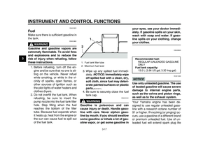
Fuel gauge
The fuel gauge indicates the amount of
fuel in the fuel tank. When the key is
turned to “ON”, the fuel gauge needle
will sweep once across the fuel level
range and then return to “E” (Empty) in
order to test the electrical circuit. The
needle moves towards “E” as the fuel
level decreases. When the needle
reaches the red zone, approximately
3.0 L (0.79 US gal, 0.66 Imp.gal) re-
main in the fuel tank. If this occurs, re-
fuel as soon as possible.
TIP
Do not allow the fuel tank to empty itself
completely.
1. Speedometer
1
1. Fuel gauge
2. Red zone
1
2
Page 21 of 94

INSTRUMENT AND CONTROL FUNCTIONS
3-6
2
34
5
6
7
8
9
EAU12182
Coolant temperature gauge
With the key in the “ON” position, the
coolant temperature gauge indicates
the temperature of the coolant. When
the key is turned to “ON”, the coolant
temperature gauge needle will sweep
once across the temperature range and
then return to “C” in order to test the
electrical circuit. The coolant tempera-
ture varies with changes in the weather
and engine load. If the needle reaches
or enters the red zone, stop the vehicle
and let the engine cool. (See
page 6-35.)
NOTICE
ECA10021
Do not continue to operate the en-
gine if it is overheating.
EAU44968
Multi-function display
WARNING
EWA12312
Be sure to stop the vehicle before
making any setting changes to the
multi-function display. Changing
settings while riding can distract the
operator and increase the risk of an
accident.
1. Coolant temperature gauge
2. Red zone
2
1
1. Tachometer
2. Tachometer red zone
3. V-belt replacement indicator “V-BELT”
4. Odometer/tripmeters
1
2
3
4
Page 22 of 94

INSTRUMENT AND CONTROL FUNCTIONS
3-7
1
2
3
4
5
6
7
8
9
The multi-function display is equipped
with the following:
�
a tachometer
�
an odometer
�
two tripmeters (which show the
distance traveled since they were
last set to zero)
�
a fuel reserve tripmeter (which
shows the distance traveled when
the remaining fuel in the fuel tank
reaches approximately 3.0 L (0.79
US gal, 0.66 Imp.gal))
�
a self-diagnosis device
�
a clock
�
an oil change tripmeter (which
shows the distance traveled since
the last engine oil change)
�
a V-belt replacement tripmeter
(which shows the distance trav-
eled since the last V-belt replace-
ment)
TIP
�
Be sure to turn the key to “ON” be-
fore using the “SELECT” and
“RESET” buttons.
�
When the key is turned to “ON”, all
of the display segments of the
multi-function display will appear
one after the other and then disap-
pear, in order to test the electrical
circuits.
Tachometer
The tachometer allows the rider to
monitor the engine speed and keep it
within the ideal power range.
NOTICE
ECA10031
Do not operate the engine in the ta-
chometer red zone.
Red zone: 8250 r/min and above
Clock
To set the clock:
1. Push the “SELECT” button and
“RESET” button together for at
least two seconds.
2. When the hour digits start flashing,
push the “RESET” button to set the
hours.
3. Push the “SELECT” button, and
the minute digits will start flashing.
4. Push the “RESET” button to set
the minutes.
5. Push the “SELECT” button and
then release it to start the clock.
1. Clock
2. Oil change indicator “OIL”
1. “RESET” button
2. “SELECT” button
1
2
1
2
Page 23 of 94

INSTRUMENT AND CONTROL FUNCTIONS
3-8
2
34
5
6
7
8
9 Odometer and tripmeter modes
Pushing the “SELECT” button switches
the display between the odometer
mode and the tripmeter modes in the
following order:
Odo
→
Trip-A
→
Trip-B
→
OIL Trip
→
V-BELT Trip
→
Odo
When approximately 3.0 L (0.79 US
gal, 0.66 Imp.gal) of fuel remains in the
fuel tank, the display will automatically
change to the fuel reserve tripmeter
mode “F Trip” and start counting the
distance traveled from that point. In that
case, pushing the “SELECT” button
switches the display between the vari-
ous tripmeter and odometer modes in
the following order:
Odo
→
F Trip
→
Trip-A
→
Trip-B
→
OILTrip
→
V-BELT Trip
→
Odo
To reset a tripmeter, select it by push-
ing the “SELECT” button until “F Trip”,
“Trip-A” or “Trip-B” is displayed. While
“F Trip”, “Trip-A” or “Trip-B” is dis-
played, push the “RESET” button for at
least one second. If you do not reset
the fuel reserve tripmeter manually, it
will reset itself automatically and the
display will return to the prior mode af-
ter refueling and traveling 5 km (3 mi).
TIP
The display cannot be changed back to
“F Trip” after pushing the “RESET” but-
ton.
1. Odometer/tripmeters
1. Oil change tripmeter
1
1
1. V-belt replacement tripmeter1
1. Fuel reserve tripmeter
1
Page 24 of 94
, then at 5000 km (3000 mi)
and every 5000 km (3000 mi)")
INSTRUMENT AND CONTROL FUNCTIONS
3-9
1
2
3
4
5
6
7
8
9Oil change indicator “OIL”
This indicator flashes at the initial 1000
km (600 mi), then at 5000 km (3000 mi)
and every 5000 km (3000 mi) thereafter
to indicate that the engine oil should be
changed.
After changing the engine oil, reset the
oil change indicator. To reset the oil
change indicator, select it by pushing
the “SELECT” button until “OIL Trip” is
displayed, and then push the “RESET”
button at least 1 second. When pushing
the “RESET” button, “OIL Trip” starts
flashing. While “OIL Trip” is flashing,
push the “RESET” button for at least 3
seconds.
If the engine oil is changed before theoil change indicator “OIL” flashes (i.e.
before the periodic oil change interval
has been reached), the indicator “OIL”
must be reset after the oil change for
the next periodic oil change to be indi-
cated at the correct time.
The electrical circuit of the indicator can
be checked according to the following
procedure.
1. Set the engine stop switch to “ ”
and turn the key to “ON”.
2. Check that the oil change indicator
comes on for a few seconds and
then goes off.
3. If the oil change indicator does not
come on, have a Yamaha dealer
check the electrical circuit.
V-belt replacement indicator
“V-BELT”
This indicator flashes every 20000 km
(12500 mi) when the V-belt needs to be
replaced.
After changing the V-belt, reset the
V-belt replacement indicator. To reset
the V-belt replacement indicator, select
it by pushing the “SELECT” button until
“V-BELT Trip” is displayed, and then
push the “RESET” button at least 1 sec-
ond. When pushing the “RESET” but-
ton, “V-BELT Trip” starts flashing.
While “V-BELT Trip” is flashing, push
the “RESET” button for at least 3 sec-
onds.
If the V-belt is changed before the
1. Oil change indicator “OIL”
1
1. V-belt replacement indicator “V-BELT”
1