2011 RENAULT SCENIC air condition
[x] Cancel search: air conditionPage 407 of 431

13B-407V9 MR-372-J84-13B450$200.mif
DIESEL INJECTION
Fault finding – Tests13B
TEST2
CONTINUED 1
High pressure circuit check
Note:
Depending on the vehicle type, the best visual access will be either from
above or from below.
Visually inspect the condition of the following components:
– outlet pipe of the compressor to the turbocharging air cooler,
– outlet pipe of the turbocharging air cooler to the inlet manifold,
– inlet manifold,
– temperature and pressure sensors.
Is one of these components incorrect (disconnected, cut, bent,
pierced or kinked pipes)?
Replace the defective parts
(see MR 364 (Mégane II) or
370 (Scénic II),
Mechanical, 12B,
Turbocharging). Exhaust system check
Visually inspect the condition of the following engine sections:
– from the exhaust manifold circuit to the turbocharger turbine,
– from the turbine outlet pipe to the end of the exhaust pipe,
– from the inlet manifold to the EGR valve
– check that the temperature and pressure sensors are connected.
Do some of these components have black or white marks on them?
Run test 6: Turbocharger control solenoid valve test.
A
YES
NO
YES
NO
AFTER REPAIRCarry out a road test followed by a complete check with the diagnostic tool.
EDC16 C36
Program No.: 91
Vdiag No.: 44, 4C, 48,
50, 54, 58
Page 408 of 431

13B-408V9 MR-372-J84-13B450$200.mif
DIESEL INJECTION
Fault finding – Tests13B
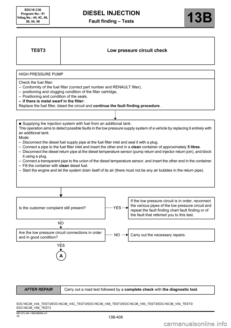
TEST3 Low pressure circuit check
HIGH PRESSURE PUMP
Check the fuel filter:
– Conformity of the fuel filter (correct part number and RENAULT filter),
– positioning and clogging condition of the filter cartridge,
– Positioning and condition of the seals.
– if there is metal swarf in the filter:
Replace the fuel filter, bleed the circuit and continue the fault finding procedure.
●Supplying the injection system with fuel from an additional tank.
This operation aims to detect possible faults in the low pressure supply system of a vehicle by replacing it entirely with
an additional tank.
Mode:
– Disconnect the diesel fuel supply pipe at the fuel filter inlet and seal it with a plug.
– Connect a pipe to the fuel filter inlet and insert the other end in a clean container of approximately 5litres.
– Disconnect the diesel return pipe at the diesel temperature sensor (pump return and injector return join), and block
it using a plug.
– Connect a transparent pipe to the union of the diesel temperature sensor, and insert the other end in the container.
– Fill the container with clean diesel fuel.
– Start the engine and let the system drain itself of its air (there must not be any air bubbles in the return pipe).
Is the customer complaint still present?If the low pressure circuit is in order, reconnect
the various pipes of the low pressure circuit and
repeat the fault finding chart fault finding or of
the fault that referred you to this test.
Are the low pressure circuit connections in order
and in good condition?Carry out the necessary repairs.
YES
NO
NO
YES
A
EDC16C36_V44_TEST3/EDC16C36_V4C_TEST3/EDC16C36_V48_TEST3/EDC16C36_V50_TEST3/EDC16C36_V54_TEST3/
EDC16C36_V58_TEST3
AFTER REPAIRCarry out a road test followed by a complete check with the diagnostic tool.
EDC16 C36
Program No.: 91
Vdiag No.: 44, 4C, 48,
50, 54, 58
Page 409 of 431

13B-409V9 MR-372-J84-13B450$200.mif
DIESEL INJECTION
Fault finding – Tests13B
TEST3
CONTINUED
Check the condition and operation of the priming bulb.
Perform repairs if necessary and continue the test.
Check the condition of all the low pressure diesel pipes from the tank to the injection pump (in particular no pinching
of pipes).
If the fault is still present with a low fuel level, check the consistency of the actual fuel level and that indicated on
the instrument panel.
– The transfer pump is supplied via a Venturi pipe mounted underneath it.
Check that the opening of the venturi (6 to 8 mm in diameter) is not blocked by dirt contained in the fuel tank.
Check the priming of the low pressure diesel circuit.
Check the conformity of the fuel used by running test 11 Diesel fuel conformity check:
– Compare the fuel with some clean diesel in order to detect petrol, solvent, thinners, sulphuric acid (fuel will have
a whitish appearance), water or fuel oil.
If the diesel fuel is not correct:
– Replace the diesel fuel.
– Change the diesel filter.
– Bleed the low and high pressure diesel circuit.
Low pressure circuit correct.
A
AFTER REPAIRCarry out a road test followed by a complete check with the diagnostic tool.
EDC16 C36
Program No.: 91
Vdiag No.: 44, 4C, 48,
50, 54, 58
Page 410 of 431

13B-410V9 MR-372-J84-13B450$200.mif
DIESEL INJECTION
Fault finding – Tests13B
TEST4 Checking the turbocharged air inlet circuit
Engine stopped:
Check the sealing of the low and high pressure air circuits (air leaks in or out, upstream/downstream of the
turbocharger).
Check the parts that are abnormally greasy of the circuit and reveal a lack of tightness.
Check:
– The condition and fitting of the ducts (foreign bodies, clogged, displaced, kinked, broken, pierced, cut, tightness
of the mounting bolts, etc.).
– the presence, condition and fitting of the seals,
– the presence and tightening of the clamps,
– the fitting of the turbocharger pressure sensor.
– the pipe and take-off point between the air duct and the turbocharging sensor
Carry out the necessary repairs
Checking the air filter.
Check:
– that the air filter unit inlet and outlet are not blocked,
– the condition and the assembly of the air filter unit (disconnected, broken, pierced, etc.),
– the cleanliness, conformity and the non-distortion of the filter element,
– The air flowmeter: run test 5: Air flowmeter.
Carry out the necessary repairs.
A
EDC16C36_V44_TEST4/EDC16C36_V4C_TEST4/EDC16C36_V48_TEST4/EDC16C36_V50_TEST4/EDC16C36_V54_TEST4/
EDC16C36_V58_TEST4
AFTER REPAIRCarry out a road test followed by a complete check with the diagnostic tool.
EDC16 C36
Program No.: 91
Vdiag No.: 44, 4C, 48,
50, 54, 58
Page 411 of 431

13B-411V9 MR-372-J84-13B450$200.mif
DIESEL INJECTION
Fault finding – Tests13B
TEST4
CONTINUED
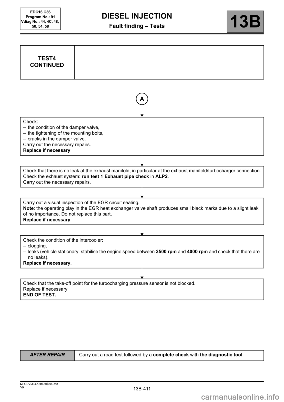
Check:
– the condition of the damper valve,
– the tightening of the mounting bolts,
– cracks in the damper valve.
Carry out the necessary repairs.
Replace if necessary.
Check that there is no leak at the exhaust manifold, in particular at the exhaust manifold/turbocharger connection.
Check the exhaust system: run test 1 Exhaust pipe check in ALP2.
Carry out the necessary repairs.
Carry out a visual inspection of the EGR circuit sealing.
Note: the operating play in the EGR heat exchanger valve shaft produces small black marks due to a slight leak
of no importance. Do not replace this part.
Replace if necessary.
Check the condition of the intercooler:
– clogging,
– leaks (vehicle stationary, stabilise the engine speed between 3500 rpm and 4000 rpm and check that there are
no leaks).
Replace if necessary.
Check that the take-off point for the turbocharging pressure sensor is not blocked.
Replace if necessary.
END OF TEST.
A
AFTER REPAIRCarry out a road test followed by a complete check with the diagnostic tool.
EDC16 C36
Program No.: 91
Vdiag No.: 44, 4C, 48,
50, 54, 58
Page 417 of 431

13B-417V9 MR-372-J84-13B450$200.mif
DIESEL INJECTION
Fault finding – Tests13B
TEST10
CONTINUED 1
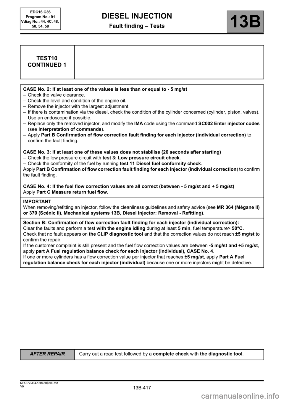
CASE No. 2: If at least one of the values is less than or equal to - 5 mg/st
– Check the valve clearance.
– Check the level and condition of the engine oil.
– Remove the injector with the largest adjustment.
– If there is contamination via the diesel, check the condition of the cylinder concerned (cylinder, piston, valves).
Use an endoscope if possible.
– Replace only the removed injector, and modify the IMA code using the command SC002 Enter injector codes
(see Interpretation of commands).
–Apply Part B Confirmation of flow correction fault finding for each injector (individual correction) to
confirm the fault finding.
CASE No. 3: If at least one of these values does not stabilise (20 seconds after starting)
– Check the low pressure circuit with test 3: Low pressure circuit check.
– Check the conformity of the fuel by running test 11 Diesel fuel conformity check.
Apply Part B Confirmation of flow correction fault finding for each injector (individual correction) to confirm
the fault finding.
CASE No. 4: If the fuel flow correction values are all correct (between - 5 mg/st and + 5 mg/st)
Apply Part C Measure return fuel flow.
IMPORTANT
When removing/refitting an injector, follow the cleanliness guidelines and safety advice (see MR 364 (Mégane II)
or 370 (Scénic II), Mechanical systems 13B, Diesel injector: Removal - Refitting).
Section B: Confirmation of flow correction fault finding for each injector (individual correction):
Clear the faults and perform a test with the engine idling during at least 5 min, fuel temperature> 50°C.
Check that no fault appears on the CLIP diagnostic tool and that the correction values do not reach ±5 mg/st to
confirm the repair.
If the customer complaint is still present and the fuel flow correction values are between -5 mg/st and +5 mg/st,
apply part A Fuel regulation balance check for each injector (individual), CASE No. 4.
If one or more cylinders has a flow correction value per injector that reaches ±5 mg/st, apply Part A Fuel
regulation balance check for each injector (individual) because one or more injectors might be defective.
AFTER REPAIRCarry out a road test followed by a complete check with the diagnostic tool.
EDC16 C36
Program No.: 91
Vdiag No.: 44, 4C, 48,
50, 54, 58
Page 423 of 431

13B-423V9 MR-372-J84-13B450$200.mif
DIESEL INJECTION
Fault finding – Tests13B
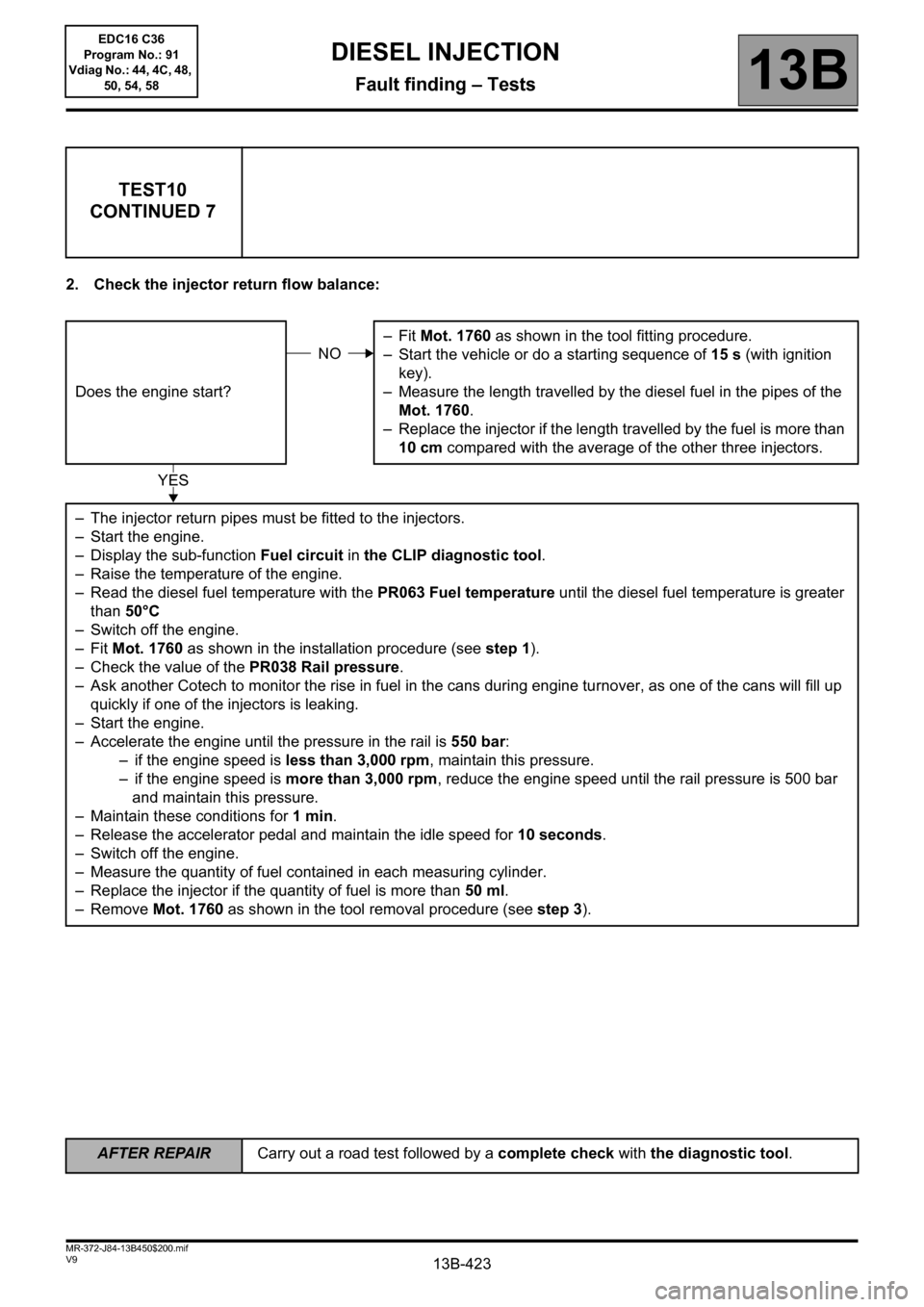
2. Check the injector return flow balance:
TEST10
CONTINUED 7
Does the engine start?–Fit Mot. 1760 as shown in the tool fitting procedure.
– Start the vehicle or do a starting sequence of 15 s (with ignition
key).
– Measure the length travelled by the diesel fuel in the pipes of the
Mot. 1760.
– Replace the injector if the length travelled by the fuel is more than
10 cm compared with the average of the other three injectors.
– The injector return pipes must be fitted to the injectors.
– Start the engine.
– Display the sub-function Fuel circuit in the CLIP diagnostic tool.
– Raise the temperature of the engine.
– Read the diesel fuel temperature with the PR063 Fuel temperature until the diesel fuel temperature is greater
than 50°C
– Switch off the engine.
–Fit Mot. 1760 as shown in the installation procedure (see step 1).
– Check the value of the PR038 Rail pressure.
– Ask another Cotech to monitor the rise in fuel in the cans during engine turnover, as one of the cans will fill up
quickly if one of the injectors is leaking.
– Start the engine.
– Accelerate the engine until the pressure in the rail is 550 bar:
– if the engine speed is less than 3,000 rpm, maintain this pressure.
– if the engine speed is more than 3,000 rpm, reduce the engine speed until the rail pressure is 500 bar
and maintain this pressure.
– Maintain these conditions for 1min.
– Release the accelerator pedal and maintain the idle speed for 10 seconds.
– Switch off the engine.
– Measure the quantity of fuel contained in each measuring cylinder.
– Replace the injector if the quantity of fuel is more than 50 ml.
– Remove Mot. 1760 as shown in the tool removal procedure (see step 3).
NO
YES
AFTER REPAIRCarry out a road test followed by a complete check with the diagnostic tool.
EDC16 C36
Program No.: 91
Vdiag No.: 44, 4C, 48,
50, 54, 58