2011 RENAULT SCENIC check
[x] Cancel search: checkPage 46 of 236

13B-46
DIESEL INJECTION
Fault finding - Interpretation of faults13B
V10 MR-372-J84-13B150$282.mif
EDC16 INJECTION
Program No.: C1
Vdiag No.: 44, 48 and 4C
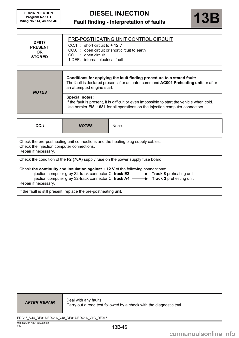
DF017
PRESENT
OR
STOREDPRE-POSTHEATING UNIT CONTROL CIRCUIT
CC.1 : short circuit to + 12 V
CC.0 : open circuit or short circuit to earth
CO : open circuit
1.DEF : internal electrical fault
NOTESConditions for applying the fault finding procedure to a stored fault:
The fault is declared present after actuator command AC001 Preheating unit, or after
an attempted engine start.
Special notes:
If the fault is present, it is difficult or even impossible to start the vehicle when cold.
Use bornier Elé. 1681 for all operations on the injection computer connectors.
CC.1
NOTESNone.
Check the pre-postheating unit connections and the heating plug supply cables.
Check the injection computer connections.
Repair if necessary.
Check the condition of the F2 (70A) supply fuse on the power supply fuse board.
Check the continuity and insulation against + 12 V of the following connections:
Injection computer grey 32-track connector C, track E2 Track 8 preheating unit
Injection computer grey 32-track connector C, track A4 Track 3 preheating unit
Repair if necessary.
If the fault is still present, replace the pre-postheating unit.
AFTER REPAIRDeal with any faults.
Carry out a road test followed by a check with the diagnostic tool.
EDC16_V44_DF017/EDC16_V48_DF017/EDC16_V4C_DF017
Page 47 of 236

13B-47
DIESEL INJECTION
Fault finding - Interpretation of faults13B
V10 MR-372-J84-13B150$282.mif
EDC16 INJECTION
Program No.: C1
Vdiag No.: 44, 48 and 4C
DF017
CONTINUED
CC.0
CO
NOTESSpecial notes:
If the pre-postheating unit has a short circuit to earth there is
a risk that the heater plugs will be operated continuously.
The heater plugs and the engine may be damaged.
Check the pre-postheating unit connections and the heating plug supply cables.
Check the injection computer connections.
Repair if necessary.
Check the condition of the F2 (70A) supply fuse on the power supply fuse board.
Check the continuity and insulation against earth of the following connection:
Injection computer grey 32-track connector C, track A4 Track 3 preheating unit
Injection computer grey 32-track connector C, track E2 Track 8 preheating unit
Repair if necessary.
If the fault is still present, replace the pre-postheating unit.
1.DEF
NOTESNone.
Check the pre-postheating unit connections and the heating plug supply cables.
Check the injection computer connections.
Repair if necessary.
Check the condition of the F2 (70A) supply fuse on the power supply fuse board.
Check for continuity and the absence of interference resistance on the following connection:
Injection computer grey 32-track connector C, track E2 Track 8 preheating unit
Repair if necessary.
If the fault is still present, check that the computer output is working correctly.
with the pre-postheating unit connected:
– connect the negative terminal of the voltmeter to track 8 of the preheating unit,
– connect the positive terminal of the voltmeter to the + 12 V battery,
– run command AC001 Pre-postheating unit.
If the voltmeter does not indicate the battery voltage while the command is running (ten one-second ON/OFF
cycles), contact the Techline.
AFTER REPAIRDeal with any faults.
Carry out a road test followed by a check with the diagnostic tool.
Page 48 of 236

13B-48
DIESEL INJECTION
Fault finding - Interpretation of faults13B
V10 MR-372-J84-13B150$282.mif
EDC16 INJECTION
Program No.: C1
Vdiag No.: 44, 48 and 4C
DF025
PRESENT
OR
STOREDPRE-POSTHEATING UNIT DIAGNOSTIC LINE
NOTESConditions for applying the fault finding procedure to a stored fault:
The fault is declared present after several attempts to start the engine, or following
actuator command AC001 Preheating unit.
Special notes:
It is difficult or even impossible to start the engine when cold.
Use bornier Elé. 1681 for all operations on the injection computer connectors.
Check the pre-postheating unit connections.
Check the connections on all the heater plugs.
Repair if necessary.
Check the resistance of the heater plugs:
Replace any plug whose resistance is not below 2Ω at + 20°C.
Check the continuity and absence of interference resistance of the following connections:
– Preheating unit track 1 Heater plug of cylinder 3
– Preheating unit track 2 Heater plug of cylinder 4
– Preheating unit track 6Heater plug of cylinder 1
– Preheating unit track 7 Heater plug of cylinder 2
Check for the presence of +12V battery on track 3 of the preheating relay (via maxi fuse).
Check the engine earthing.
If the fault is still present,
Check the injection computer connections.
Check for continuity and the absence of interference resistance on the following connection:
Injection computer, grey 32-track connector C, track A4 Track 9 preheating unit connector
If the fault is still present, replace the pre-postheating unit.
AFTER REPAIRDeal with any faults.
Carry out a road test followed by a check with the diagnostic tool.
EDC16_V44_DF025/EDC16_V48_DF025/EDC16_V4C_DF025
Page 49 of 236

13B-49
DIESEL INJECTION
Fault finding - Interpretation of faults13B
V10 MR-372-J84-13B150$282.mif
EDC16 INJECTION
Program No.: C1
Vdiag No.: 44, 48 and 4C
DF037
PRESENT
OR
STOREDENGINE IMMOBILISER
NOTESConditions for applying the fault finding procedure to a stored fault:
The fault is declared present after a road test or an attempt to start the engine.
Special notes:
It is impossible to start the vehicle.
Use bornier Elé. 1681 for all operations on the injection computer connectors.
Check the UCH connections.
Check the injection computer connections.
Repair if necessary.
Test the multiplex network and carry out a complete fault finding procedure on the UCH.
Refer to the UCH Technical Note if a fault is declared present.
If the fault is still present, contact the Techline.
AFTER REPAIRDeal with any faults.
Carry out a road test followed by a check with the diagnostic tool.
EDC16_V44_DF037/EDC16_V48_DF037/EDC16_V4C_DF037
Page 50 of 236

13B-50
DIESEL INJECTION
Fault finding - Interpretation of faults13B
V10 MR-372-J84-13B150$282.mif
EDC16 INJECTION
Program No.: C1
Vdiag No.: 44, 48 and 4C
DF038
PRESENT
OR
STORED
COMPUTER
CO : open circuit
1.DEF : permanent high signal
2.DEF : permanent low signal
3.DEF : configuration absent or incorrect
4.DEF : analogue/digital converter fault
5.DEF : EEPROM fault
6.DEF : activation in Watchdog
7.DEF : signal outside upper limit
8.DEF : signal outside lower limit
9.DEF : disrupted communication
10.DEF : injector control condenser fault
11.DEF : injector control
12.DEF : Initialisation fault
13.DEF : deceleration fault when decelerating
NOTESConditions for applying the fault finding procedure to a stored fault:
The fault is declared present after several starting attempts, or with the engine running.
Special notes:
The level 1 warning light is lit for a fault that does not require you to stop the vehicle.
The level 2 warning light is lit for a fault which requires the engine to be switched off.
If 5.DEF is still present, the OBD warning light will come on after three consecutive
driving cycles (starting + 5 seconds + switch off the ignition and wait 40 seconds).
Use bornier Elé. 1681 for all operations on the injection computer connectors.
CO
1.DEF
to
9.DEF
11.DEF
to
13.DEFCheck the injection computer connections and the continuity of all the supplies.
Repair if necessary.
Clear the faults.
Switch off the ignition, wait 30 seconds and switch the ignition on again.
If the fault is still present, contact the Techline and fill out the fault finding log included
in this Technical Note.
AFTER REPAIRDeal with any faults.
Carry out a road test followed by a check with the diagnostic tool.
EDC16_V44_DF038/EDC16_V48_DF038/EDC16_V4C_DF038
Page 51 of 236

DIESEL INJECTION
Fault finding - Interpretation of faults13B
13B-51V10 MR-372-J84-13B150$282.mif
EDC16 INJECTION
Program No.: C1
Vdiag No.: 44, 48 and 4C
DF038
CONTINUED
10.DEF
NOTESIf there are a number of faults, deal with the other system
faults first.
NODisplay the stored context for fault DF038.
PR142 Computer fault = 10YES
Contact the Techline
NOParameters of main screen PR071 Computer
supply voltage > 10 V.YES
NOContexts stored for DF038
PR071 Computer supply voltage > 10 V.
YES
– Check the condition of the wiring harness
between the computer and the battery, carry
out the necessary repairs.
– Start the vehicle.
– Clear the stored faults.
– Check the faults:
– If DF038 is absent, end of fault finding.
– If DF038 is present, contact the Techline.
– Check the charge circuit and carry out the
necessary repairs:
– Check the condition of the battery terminals,
– Carry out fault finding on the alternator.
Recharge or replace the battery.
AFTER REPAIRDeal with any faults.
Carry out a road test followed by a check with the diagnostic tool.
Page 52 of 236

13B-52
DIESEL INJECTION
Fault finding - Interpretation of faults13B
V10 MR-372-J84-13B150$282.mif
EDC16 INJECTION
Program No.: C1
Vdiag No.: 44, 48 and 4C
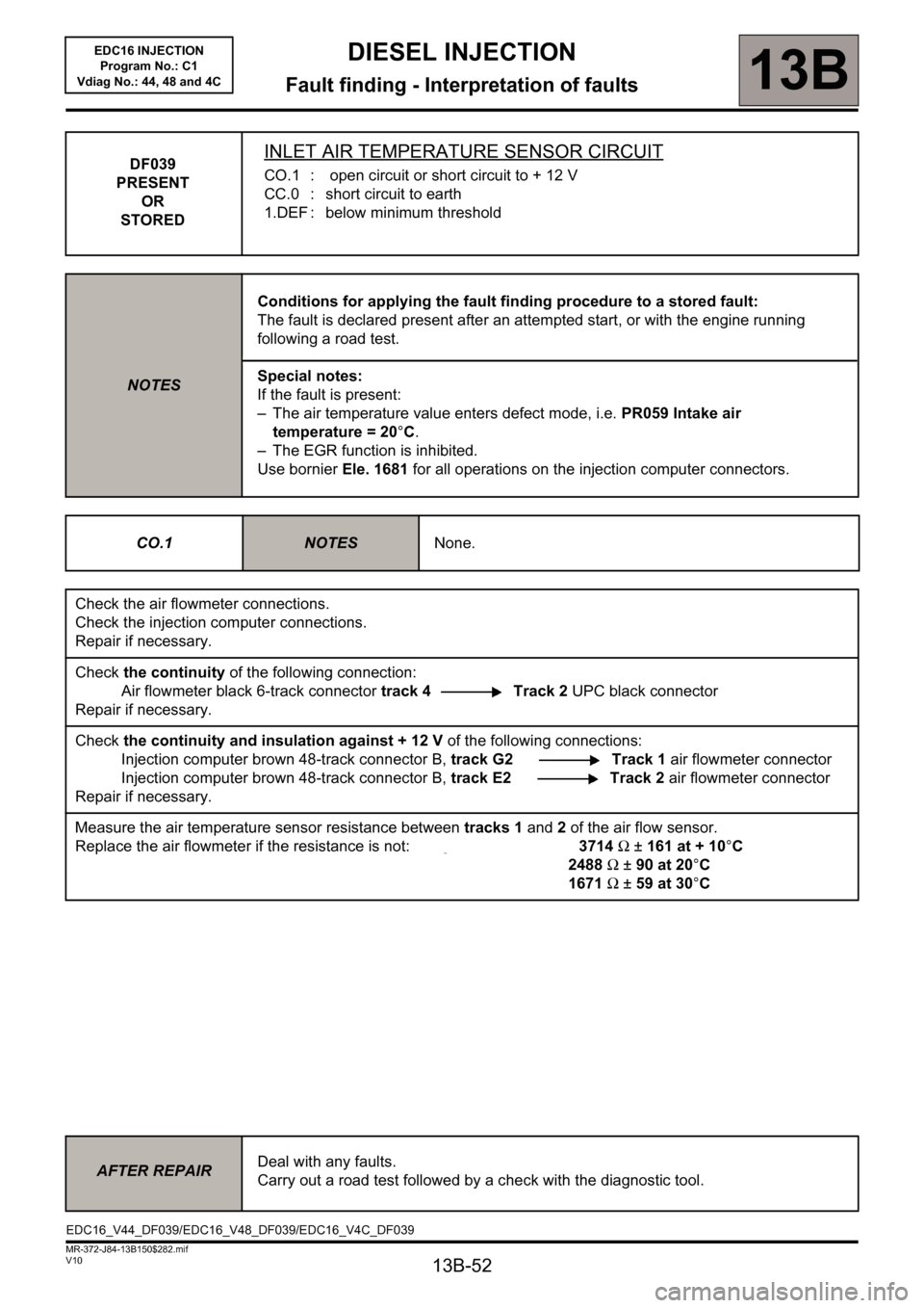
DF039
PRESENT
OR
STOREDINLET AIR TEMPERATURE SENSOR CIRCUIT
CO.1 : open circuit or short circuit to + 12 V
CC.0 : short circuit to earth
1.DEF : below minimum threshold
NOTESConditions for applying the fault finding procedure to a stored fault:
The fault is declared present after an attempted start, or with the engine running
following a road test.
Special notes:
If the fault is present:
– The air temperature value enters defect mode, i.e. PR059 Intake air
temperature = 20°C.
– The EGR function is inhibited.
Use bornier Ele. 1681 for all operations on the injection computer connectors.
CO.1
NOTESNone.
Check the air flowmeter connections.
Check the injection computer connections.
Repair if necessary.
Check the continuity of the following connection:
Air flowmeter black 6-track connector track 4 Track 2 UPC black connector
Repair if necessary.
Check the continuity and insulation against + 12 V of the following connections:
Injection computer brown 48-track connector B, track G2 Track 1 air flowmeter connector
Injection computer brown 48-track connector B, track E2 Track 2 air flowmeter connector
Repair if necessary.
Measure the air temperature sensor resistance between tracks 1 and 2 of the air flow sensor.
Replace the air flowmeter if the resistance is not: 3714Ω ±161 at + 10°C
2488 Ω ± 90 at 20°C
1671 Ω ± 59 at 30°C
AFTER REPAIRDeal with any faults.
Carry out a road test followed by a check with the diagnostic tool.
EDC16_V44_DF039/EDC16_V48_DF039/EDC16_V4C_DF039
Page 53 of 236

13B-53
DIESEL INJECTION
Fault finding - Interpretation of faults13B
V10 MR-372-J84-13B150$282.mif
EDC16 INJECTION
Program No.: C1
Vdiag No.: 44, 48 and 4C
DF039
CONTINUED 1
CC.0
NOTESNone.
Check the air flowmeter connections.
Check the injection computer connections.
Repair if necessary.
Check the continuity and insulation against earth of the following connections:
Injection computer brown 48-track connector B, track G2 Track 1 air flowmeter
Air flowmeter black 6-track connector track 4 Track 2 UPC black connector
Injection computer brown 48-track connector B, track B4 Track 3 air flowmeter
Repair if necessary.
Measure the resistance of the air temperature sensor integrated into the flowmeter across tracks 1 and 2.
Replace the air flowmeter if the resistance is not: 3714Ω ±161 at + 10°C
2488 Ω ± 90 at 20°C
1671 Ω ± 59 at 30°C
AFTER REPAIRDeal with any faults.
Carry out a road test followed by a check with the diagnostic tool.