2011 NISSAN TIIDA brake sensor
[x] Cancel search: brake sensorPage 1249 of 3787

DI-10
< SERVICE INFORMATION >
COMBINATION METERS
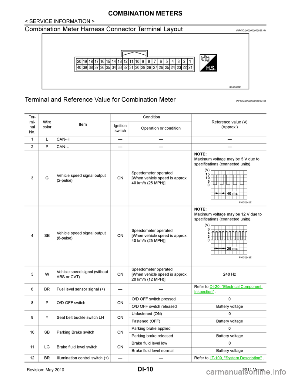
Combination Meter Harness Connector Terminal Layout
INFOID:0000000005929164
Terminal and Reference Va lue for Combination MeterINFOID:0000000005929165
LKIA0698E
Te r -
mi-nal
No. Wire
color Item Condition
Reference value (V)(Approx.)
Ignition
switch Operation or condition
1LCAN-H —— —
2PCAN-L —— —
3G Vehicle speed signal output
(2-pulse) ONSpeedometer operated
[When vehicle speed is approx.
40 km/h (25 MPH)] NOTE:
Maximum voltage may be 5 V due to
specifications (connected units).
4SB Vehicle speed signal output
(8-pulse) ONSpeedometer operated
[When vehicle speed is approx.
40 km/h (25 MPH)] NOTE:
Maximum voltage may be 12 V due to
specifications (connected units).
5W Vehicle speed signal (without
ABS or CVT) ONSpeedometer operated
[When vehicle speed is approx.
20 km/h (12 MPH)] 240 Hz
6 BR Fuel level sensor signal (+) — —Refer to DI-20, "
Electrical Component
Inspection" .
8 P O/D OFF switch ONO/D OFF switch pressed
0
O/D OFF switch released Battery voltage
9 Y Seat belt buckle switch LH ON Unfastened (ON)
0
Fastened (OFF) Battery voltage
10 SB Parking Brake switch ONParking brake applied
0
Parking brake released Battery voltage
11 LG Brake fluid level switch ON Brake fluid level low
0
Brake fluid level normal Battery voltage
12 BR Illumination control switch (+) — —Refer to LT- 1 0 9 , "
System Description" .
PKIC0642E
PKIC0643E
Revision: May 2010 2011 Versa
Page 1250 of 3787

COMBINATION METERSDI-11
< SERVICE INFORMATION >
C
DE
F
G H
I
J
L
M A
B
DI
N
O P
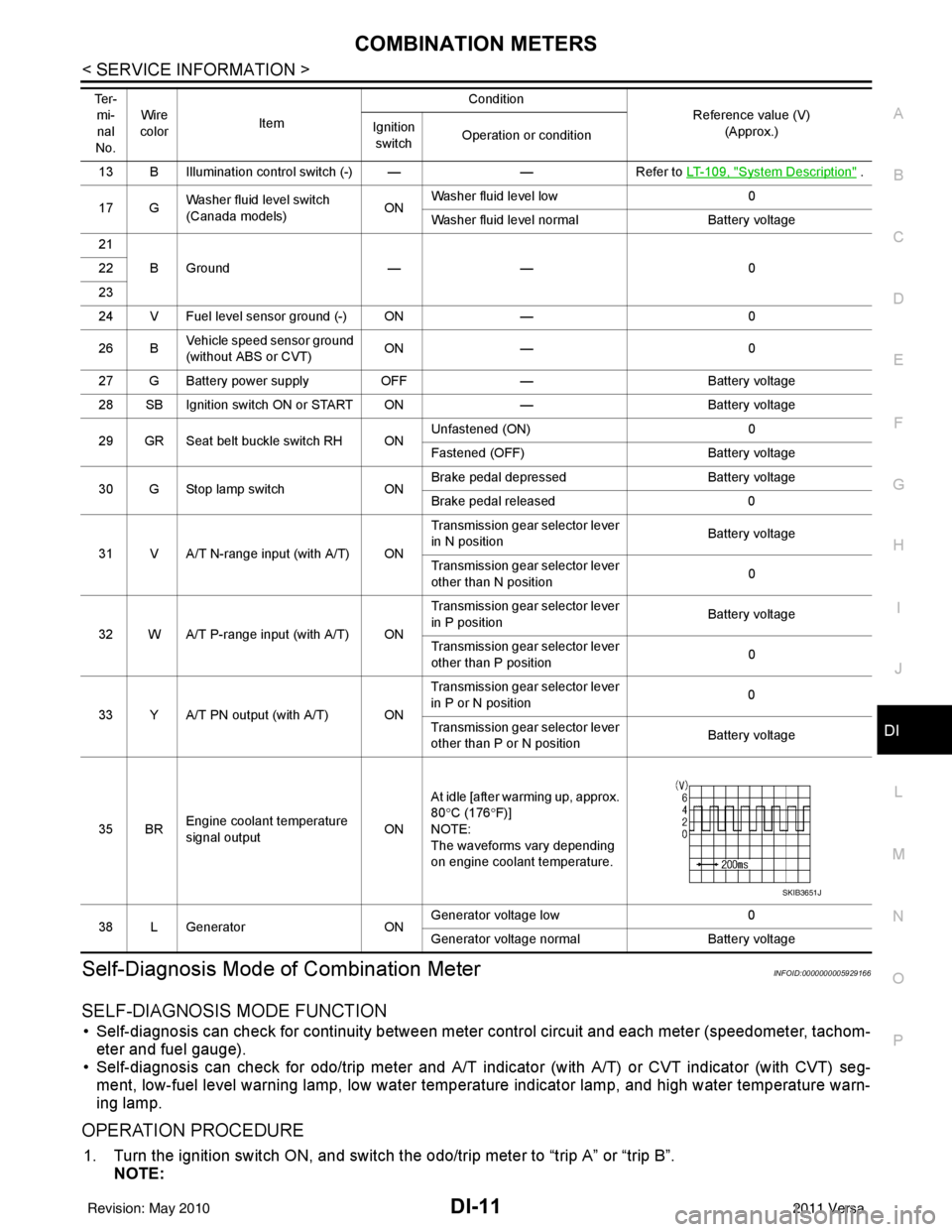
Self-Diagnosis Mode of Combination MeterINFOID:0000000005929166
SELF-DIAGNOSIS MODE FUNCTION
• Self-diagnosis can check for continuity between meter control circuit and each meter (speedometer, tachom- eter and fuel gauge).
• Self-diagnosis can check for odo/trip meter and A/T indi cator (with A/T) or CVT indicator (with CVT) seg-
ment, low-fuel level warning lamp, low water temperature indicator lamp, and high water temperature warn-
ing lamp.
OPERATION PROCEDURE
1. Turn the ignition switch ON, and switch the odo/trip meter to “trip A” or “trip B”. NOTE:
13 B Illumination control switch (-) — —Refer to LT- 1 0 9 , "System Description" .
17 G Washer fluid level switch
(Canada models)
ONWasher fluid level low
0
Washer fluid level normal Battery voltage
21 BGround —— 0
22
23
24 V Fuel level sensor ground (-) ON —0
26 B Vehicle speed sensor ground
(without ABS or CVT) ON
— 0
27 G Battery power supply OFF— Battery voltage
28 SB Ignition switch ON or START ON —Battery voltage
29 GR Seat belt buckle switch RH ON Unfastened (ON)
0
Fastened (OFF) Battery voltage
30 G Stop lamp switch ONBrake pedal depressed
Battery voltage
Brake pedal released 0
31 V A/T N-range input (with A/T) ON Transmission gear selector lever
in N position
Battery voltage
Transmission gear selector lever
other than N position 0
32 W A/T P-range input (with A/T) ON Transmission gear selector lever
in P position
Battery voltage
Transmission gear selector lever
other than P position 0
33 Y A/T PN output (with A/T) ON Transmission gear selector lever
in P or N position
0
Transmission gear selector lever
other than P or N position Battery voltage
35 BR Engine coolant temperature
signal output
ONAt idle [after warming up, approx.
80
°C (176 °F)]
NOTE:
The waveforms vary depending
on engine coolant temperature.
38 L Generator ONGenerator voltage low
0
Generator voltage no rmal Battery voltage
Te r -
mi-
nal
No. Wire
color Item Condition
Reference value (V)
(Approx.)
Ignition
switch Operation or condition
SKIB3651J
Revision: May 2010
2011 Versa
Page 1284 of 3787

WARNING CHIMEDI-45
< SERVICE INFORMATION >
C
DE
F
G H
I
J
L
M A
B
DI
N
O P
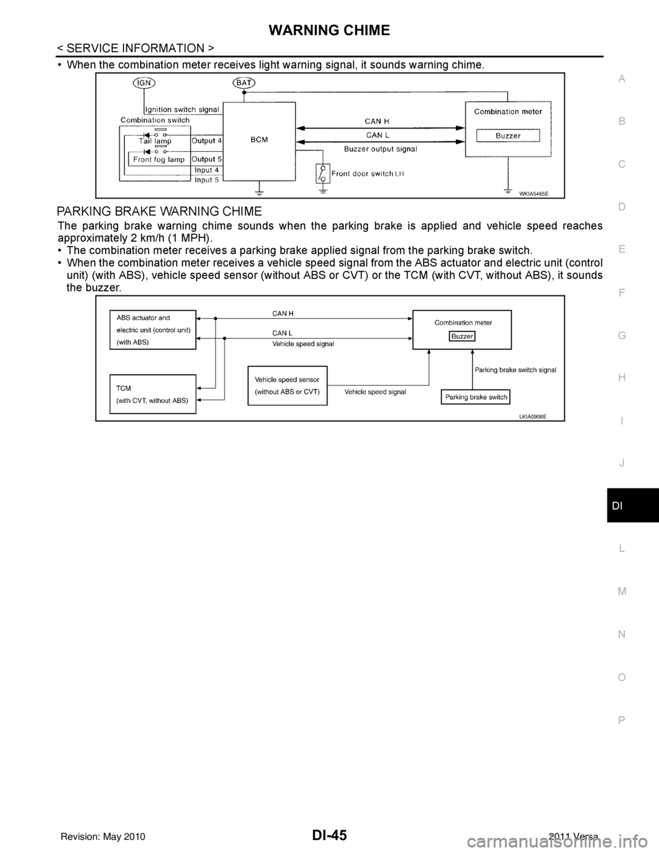
• When the combination meter receives light warning signal, it sounds warning chime.
PARKING BRAKE WARNING CHIME
The parking brake warning chime sounds when the parking brake is applied and vehicle speed reaches
approximately 2 km/h (1 MPH).
• The combination meter receives a parking brake applied signal from the parking brake switch.
• When the combination meter receives a vehicle speed si gnal from the ABS actuator and electric unit (control
unit) (with ABS), vehicle speed sensor (without ABS or CVT) or the TCM (with CVT, without ABS), it sounds
the buzzer.
WKIA5465E
LKIA0906E
Revision: May 2010 2011 Versa
Page 1299 of 3787

EC-5
C
DE
F
G H
I
J
K L
M
EC A
N
O P
Component Inspection (Fuel filler cap) ...............
..
344
Component Inspection (Drain filter) ......................345
P0460 FUEL LEVEL SENSOR ...................... ..346
Description .......................................................... ..346
DTC Logic .............................................................346
Diagnosis Procedure .............................................346
P0461 FUEL LEVEL SENSOR ........................347
Description .......................................................... ..347
DTC Logic .............................................................347
Component Function Check ..................................347
Diagnosis Procedure .............................................348
P0462, P0463 FUEL LEVEL SENSOR ............349
Description .......................................................... ..349
DTC Logic .............................................................349
Diagnosis Procedure .............................................349
P0500 VSS .......................................................351
Description .......................................................... ..351
DTC Logic .............................................................351
Component Function Check ..................................352
Diagnosis Procedure .............................................352
P0506 ISC SYSTEM .........................................353
Description .......................................................... ..353
DTC Logic .............................................................353
Diagnosis Procedure .............................................353
P0507 ISC SYSTEM .........................................355
Description .......................................................... ..355
DTC Logic .............................................................355
Diagnosis Procedure .............................................355
P0603 ECM POWER SUPPLY .........................357
Description .......................................................... ..357
DTC Logic .............................................................357
Diagnosis Procedure .............................................357
P0605 ECM .......................................................359
Description ............................................................359
DTC Logic .............................................................359
Diagnosis Procedure .............................................360
P0607 ECM .......................................................361
Description ............................................................361
DTC Logic .............................................................361
Diagnosis Procedure .............................................361
P0643 SENSOR POWER SUPPLY .................362
DTC Logic ........................................................... ..362
Wiring Diagram .....................................................363
Diagnosis Procedure .............................................363
P0850 PNP SWITCH ........................................366
Description ............................................................366
DTC Logic .............................................................366
Component Function Check ..................................367
Wiring Diagram .....................................................368
Diagnosis Procedure .............................................368
P1148 CLOSED LOOP CONTROL ................371
DTC Logic ............................................................ ..371
P1217 ENGINE OVER TEMPERATURE ........372
DTC Logic ..............................................................372
Component Function Check ..................................372
Diagnosis Procedure .............................................373
P1225 TP SENSOR .........................................376
Description .............................................................376
DTC Logic ..............................................................376
Diagnosis Procedure .............................................376
Special Repair Requirement ..................................377
P1226 TP SENSOR .........................................378
Description .............................................................378
DTC Logic ..............................................................378
Diagnosis Procedure .............................................378
Special Repair Requirement ..................................379
P1421 COLD START CONTROL ...................380
Description .............................................................380
DTC Logic ..............................................................380
Diagnosis Procedure .............................................380
P1715 INPUT SPEED SENSOR (PRIMARY
SPEED SENSOR) ...........................................
382
Description ........................................................... ..382
DTC Logic ..............................................................382
Diagnosis Procedure .............................................382
P1805 BRAKE SWITCH .................................383
Description .............................................................383
DTC Logic ..............................................................383
Wiring Diagram ......................................................384
Diagnosis Procedure .............................................384
Component Inspection (Stop Lamp Switch) ..........386
P2100, P2103 THROTTLE CONTROL MO-
TOR RELAY ....................................................
387
Description .............................................................387
DTC Logic ..............................................................387
Wiring Diagram ......................................................388
Diagnosis Procedure .............................................388
P2101 ELECTRIC THROTTLE CONTROL
FUNCTION ......................................................
391
Description ........................................................... ..391
DTC Logic ..............................................................391
Wiring Diagram ......................................................392
Diagnosis Procedure .............................................392
Component Inspection ...........................................395
Special Repair Requirement ..................................395
P2118 THROTTLE CONTROL MOTOR .........396
Description .............................................................396
DTC Logic ..............................................................396
Wiring Diagram ......................................................397
Diagnosis Procedure .............................................397
Component Inspection ...........................................398
Special Repair Requirement ..................................399
Revision: May 2010 2011 Versa
Page 1306 of 3787

EC-12
Description .............................................................889
On Board Diagnosis Logic .....................................889
DTC Confirmation Procedure ................................889
Diagnosis Procedure .............................................889
DTC P0507 ISC SYSTEM ................................891
Description ........................................................... ..891
On Board Diagnosis Logic .....................................891
DTC Confirmation Procedure ................................891
Diagnosis Procedure .............................................891
DTC P050A, P050B, P050E COLD START
CONTROL ........................................................
893
Description ........................................................... ..893
On Board Diagnosis Logic .....................................893
DTC Confirmation Procedure ................................893
Diagnosis Procedure .............................................894
DTC P0605 ECM ..............................................895
Component Description ....................................... ..895
On Board Diagnosis Logic .....................................895
DTC Confirmation Procedure ................................895
Diagnosis Procedure .............................................896
DTC P0607 ECM ..............................................897
Description ........................................................... ..897
On Board Diagnosis Logic .....................................897
DTC Confirmation Procedure ................................897
Diagnosis Procedure .............................................897
DTC P0643 SENSOR POWER SUPPLY ........898
On Board Diagnosis Logic ................................... ..898
DTC Confirmation Procedure ................................898
Wiring Diagram ......................................................899
Diagnosis Procedure .............................................900
DTC P0850 PNP SWITCH ...............................903
Component Description ....................................... ..903
CONSULT-III Reference Value in Data Monitor
Mode .................................................................... ..
903
On Board Diagnosis Logic .....................................903
DTC Confirmation Procedure ................................903
Overall Function Check .........................................904
Wiring Diagram ......................................................905
Diagnosis Procedure .............................................906
DTC P1148 CLOSED LOOP CONTROL .........909
On Board Diagnosis Logic ................................... ..909
DTC P1211 TCS CONTROL UNIT ..................910
Description ........................................................... ..910
On Board Diagnosis Logic .....................................910
DTC Confirmation Procedure ................................910
Diagnosis Procedure .............................................910
DTC P1212 TCS COMMUNICATION LINE .....911
Description ........................................................... ..911
On Board Diagnosis Logic .....................................911
DTC Confirmation Procedure ................................911
Diagnosis Procedure .............................................911
DTC P1217 ENGINE OVER TEMPERATURE ..912
System Description .............................................. .912
CONSULT-III Reference Value in Data Monitor
Mode .................................................................... .
913
On Board Diagnosis Logic ....................................913
Overall Function Check .........................................913
Wiring Diagram .....................................................915
Diagnosis Procedure .............................................916
Main 13 Causes of Overheating ...........................919
Component Inspection ..........................................920
DTC P1225 TP SENSOR ..................................921
Component Description ....................................... .921
On Board Diagnosis Logic ....................................921
DTC Confirmation Procedure ................................921
Diagnosis Procedure .............................................921
Removal and Installation .......................................922
DTC P1226 TP SENSOR ................................ ..923
Component Description ....................................... .923
On Board Diagnosis Logic ....................................923
DTC Confirmation Procedure ................................923
Diagnosis Procedure .............................................923
Removal and Installation .......................................924
DTC P1564 ASCD STEERING SWITCH ........ ..925
Component Description ....................................... .925
CONSULT-III Reference Value in Data Monitor
Mode .................................................................... .
925
On Board Diagnosis Logic ....................................925
DTC Confirmation Procedure ................................926
Wiring Diagram .....................................................927
Diagnosis Procedure .............................................928
Component Inspection ..........................................930
DTC P1572 ASCD BRAKE SWITCH ...............931
Component Description ....................................... .931
CONSULT-III Reference Value in Data Monitor
Mode .................................................................... .
931
On Board Diagnosis Logic ....................................931
DTC Confirmation Procedure ................................932
Wiring Diagram .....................................................933
Diagnosis Procedure .............................................934
Component Inspection ..........................................938
DTC P1574 ASCD VEHICLE SPEED SEN-
SOR ..................................................................
940
Component Description ....................................... .940
On Board Diagnosis Logic ....................................940
DTC Confirmation Procedure ................................940
Diagnosis Procedure .............................................940
DTC P1715 INPUT SPEED SENSOR ..............942
A/T .......................................................................... .942
A/T : Description ...................................................942
A/T : CONSULT-III Reference Value in Data Mon-
itor Mode ...............................................................
942
A/T : On Board Diagnosis Logic ............................942
A/T : Diagnosis Procedure ....................................942
Revision: May 2010 2011 Versa
Page 1307 of 3787

EC-13
C
DE
F
G H
I
J
K L
M
EC A
N
O P
CVT ........................................................................
..
942
CVT : Description ..................................................942
CVT : CONSULT-III Reference Value in Data
Monitor Mode ...................................................... ..
942
CVT : On Board Diagnosis Logic ..........................943
CVT : DTC Confirmation Procedure ......................943
CVT : Diagnosis Procedure ...................................943
DTC P1805 BRAKE SWITCH ..........................944
Description .......................................................... ..944
CONSULT-III Reference Value in Data Monitor
Mode ................................................................... ..
944
On Board Diagnosis Logic ....................................944
DTC Confirmation Procedure ................................944
Wiring Diagram .....................................................945
Diagnosis Procedure .............................................946
Component Inspection ..........................................947
DTC P2100, P2103 THROTTLE CONTROL
MOTOR RELAY ...............................................
948
Component Description ....................................... ..948
CONSULT-III Reference Value in Data Monitor
Mode ................................................................... ..
948
On Board Diagnosis Logic ....................................948
DTC Confirmation Procedure ................................948
Wiring Diagram .....................................................949
Diagnosis Procedure .............................................950
DTC P2101 ELECTRIC THROTTLE CON-
TROL FUNCTION ........................................... ..
952
Description .......................................................... ..952
On Board Diagnosis Logic ....................................952
DTC Confirmation Procedure ................................952
Wiring Diagram .....................................................953
Diagnosis Procedure .............................................954
Component Inspection ..........................................957
Removal and Installation .......................................957
DTC P2118 THROTTLE CONTROL MOTOR ..958
Component Description ....................................... ..958
On Board Diagnosis Logic ....................................958
DTC Confirmation Procedure ................................958
Wiring Diagram .....................................................959
Diagnosis Procedure .............................................960
Component Inspection ..........................................961
Removal and Installation .......................................961
DTC P2119 ELECTRIC THROTTLE CON-
TROL ACTUATOR ...........................................
963
Component Description ....................................... ..963
On Board Diagnosis Logic ....................................963
DTC Confirmation Procedure ................................963
Diagnosis Procedure .............................................964
DTC P2122, P2123 APP SENSOR ..................965
Component Description ....................................... ..965
CONSULT-III Reference Value in Data Monitor
Mode ................................................................... ..
965
On Board Diagnosis Logic ....................................965
DTC Confirmation Procedure ................................965
Wiring Diagram .................................................... ..966
Diagnosis Procedure .............................................967
Component Inspection ...........................................969
Removal and Installation .......................................969
DTC P2127, P2128 APP SENSOR .................970
Component Description .........................................970
CONSULT-III Reference Value in Data Monitor
Mode .................................................................... ..
970
On Board Diagnosis Logic .....................................970
DTC Confirmation Procedure ................................971
Wiring Diagram ......................................................972
Diagnosis Procedure .............................................973
Component Inspection ...........................................975
Removal and Installation .......................................976
DTC P2135 TP SENSOR ................................977
Component Description .........................................977
CONSULT-III Reference Value in Data Monitor
Mode .................................................................... ..
977
On Board Diagnosis Logic .....................................977
DTC Confirmation Procedure ................................977
Wiring Diagram ......................................................978
Diagnosis Procedure .............................................979
Component Inspection ...........................................981
Removal and Installation .......................................981
DTC P2138 APP SENSOR .............................982
Component Description .........................................982
CONSULT-III Reference Value in Data Monitor
Mode .................................................................... ..
982
On Board Diagnosis Logic .....................................982
DTC Confirmation Procedure ................................983
Wiring Diagram ......................................................984
Diagnosis Procedure .............................................985
Component Inspection ...........................................988
Removal and Installation .......................................988
DTC P2A00 A/F SENSOR 1 ...........................989
Component Description .........................................989
CONSULT-III Reference Value in Data Monitor
Mode .................................................................... ..
989
On Board Diagnosis Logic .....................................989
DTC Confirmation Procedure ................................989
Wiring Diagram ......................................................991
Diagnosis Procedure .............................................992
Removal and Installation .......................................995
ASCD BRAKE SWITCH ..................................996
Component Description .........................................996
CONSULT-III Reference Value in Data Monitor
Mode .................................................................... ..
996
Wiring Diagram ......................................................997
Diagnosis Procedure .............................................998
Component Inspection .........................................1002
ASCD INDICATOR .........................................1004
Component Description .......................................1004
CONSULT-III Reference Value in Data Monitor
Mode ....................................................................
1004
Revision: May 2010 2011 Versa
Page 1320 of 3787
![NISSAN TIIDA 2011 Service Repair Manual EC-26
< BASIC INSPECTION >[HR16DE]
INSPECTION AND ADJUSTMENT
• Each time electric throttle control actuator or ECM is replaced.
• Idle speed or ignition timing is out of specification.
IDLE AIR VO NISSAN TIIDA 2011 Service Repair Manual EC-26
< BASIC INSPECTION >[HR16DE]
INSPECTION AND ADJUSTMENT
• Each time electric throttle control actuator or ECM is replaced.
• Idle speed or ignition timing is out of specification.
IDLE AIR VO](/manual-img/5/57396/w960_57396-1319.png)
EC-26
< BASIC INSPECTION >[HR16DE]
INSPECTION AND ADJUSTMENT
• Each time electric throttle control actuator or ECM is replaced.
• Idle speed or ignition timing is out of specification.
IDLE AIR VOLUME LEARNING
: Special Repair RequirementINFOID:0000000005929760
1.PRECONDITIONING
Make sure that all of the following conditions are satisfied.
Learning will be cancelled if any of the follo wing conditions are missed for even a moment.
• Battery voltage: More than 12.9 V (At idle)
• Engine coolant temperature: 70 - 100 °C (158 - 212° F)
• Selector lever: P or N (A/T), Neutral (M/T)
• Electric load switch: OFF (Air conditioner, headlamp, rear window defogger)
On vehicles equipped with daytime light systems, if the parking brake is applied before the engine is
started the headlamp will not be illuminated.
• Steering wheel: Neutral (Straight-ahead position)
• Vehicle speed: Stopped
• Transmission: Warmed-up
- A/T models
• With CONSULT-III: Drive vehicle until “FLUID TEMP SE” in “DATA MONITOR” mode of “TRANSMISSION”
system indicates less than 0.9 V.
• Without CONSULT-III: Drive vehicle for 10 minutes.
- M/T models
• Drive vehicle for 10 minutes.
Do you have CONSULT-III?
YES >> GO TO 2.
NO >> GO TO 3.
2.IDLE AIR VOLUME LEARNING
With CONSULT-III
1. Perform Accelerator Pedal Released Position Learning. Refer to EC-25, "
ACCELERATOR PEDAL
RELEASED POSITION LEARNING : Special Repair Requirement".
2. Perform Throttle Valve Closed Position Learning. Refer to EC-25, "
THROTTLE VALVE CLOSED POSI-
TION LEARNING : Special Repair Requirement".
3. Start engine and warm it up to normal operating temperature.
4. Select “IDLE AIR VOL LEARN” in “WORK SUPPORT” mode.
5. Touch “START” and wait 20 seconds.
Is
“CMPLT” displayed on CONSULT-III screen?
YES >> GO TO 4.
NO >> GO TO 5.
3.IDLE AIR VOLUME LEARNING
Without CONSULT-III
NOTE:
• It is better to count the ti me accurately with a clock.
• It is impossible to switch the di agnostic mode when an accelerator pedal position sensor circuit has
a malfunction.
1. Perform Accelerator Pedal Released Position Learning. Refer to EC-25, "
ACCELERATOR PEDAL
RELEASED POSITION LEARNING : Special Repair Requirement".
2. Perform Throttle Valve Closed Position Learning. Refer to EC-25, "
THROTTLE VALVE CLOSED POSI-
TION LEARNING : Special Repair Requirement".
3. Start engine and warm it up to normal operating temperature.
4. Turn ignition switch OFF and wait at least 10 seconds.
5. Confirm that accelerator pedal is fully releas ed, turn ignition switch ON and wait 3 seconds.
6. Repeat the following procedure quickly five times within 5 seconds.
- Fully depress the accelerator pedal.
- Fully release the accelerator pedal.
7. Wait 7 seconds, fully depress the accelerator pedal and keep it for approx. 20 seconds until the MIL stops
blinking and turned ON.
8. Fully release the accelerator pedal within 3 seconds after the MIL turned ON.
Revision: May 2010 2011 Versa
Page 1339 of 3787
![NISSAN TIIDA 2011 Service Repair Manual ENGINE CONTROL SYSTEMEC-45
< FUNCTION DIAGNOSIS > [HR16DE]
C
D
E
F
G H
I
J
K L
M A
EC
NP
O
Component DescriptionINFOID:0000000005929766
1. Cooling fan motor harness connec-
tor 2. Crankshaft position NISSAN TIIDA 2011 Service Repair Manual ENGINE CONTROL SYSTEMEC-45
< FUNCTION DIAGNOSIS > [HR16DE]
C
D
E
F
G H
I
J
K L
M A
EC
NP
O
Component DescriptionINFOID:0000000005929766
1. Cooling fan motor harness connec-
tor 2. Crankshaft position](/manual-img/5/57396/w960_57396-1338.png)
ENGINE CONTROL SYSTEMEC-45
< FUNCTION DIAGNOSIS > [HR16DE]
C
D
E
F
G H
I
J
K L
M A
EC
NP
O
Component DescriptionINFOID:0000000005929766
1. Cooling fan motor harness connec-
tor 2. Crankshaft position sensor 3. Stop lamp switch
4. Brake pedal 5. Accelerator pedal position sensor
harness connector 6. Accelerator pedal position sensor
7. Accelerator pedal 8. Fuel level sensor unit and fuel pump
harness connector (view with in-
spection hole cover removed) 9. Fuel pressure regulator
10. Fuel pump
AWBIA0044ZZ
Component Reference
A/F sensor 1 EC-185, "
Description"
A/F sensor 1 heaterEC-138, "Description"
Accelerator pedal position sensorEC-402, "Description"
Camshaft position sensor (PHASE)EC-272, "Description"
Revision: May 2010 2011 Versa