2011 NISSAN TIIDA brake sensor
[x] Cancel search: brake sensorPage 2649 of 3787

FRONT WHEEL HUB AND KNUCKLEFAX-7
< SERVICE INFORMATION >
CEF
G H
I
J
K L
M A
B
FA X
N
O P
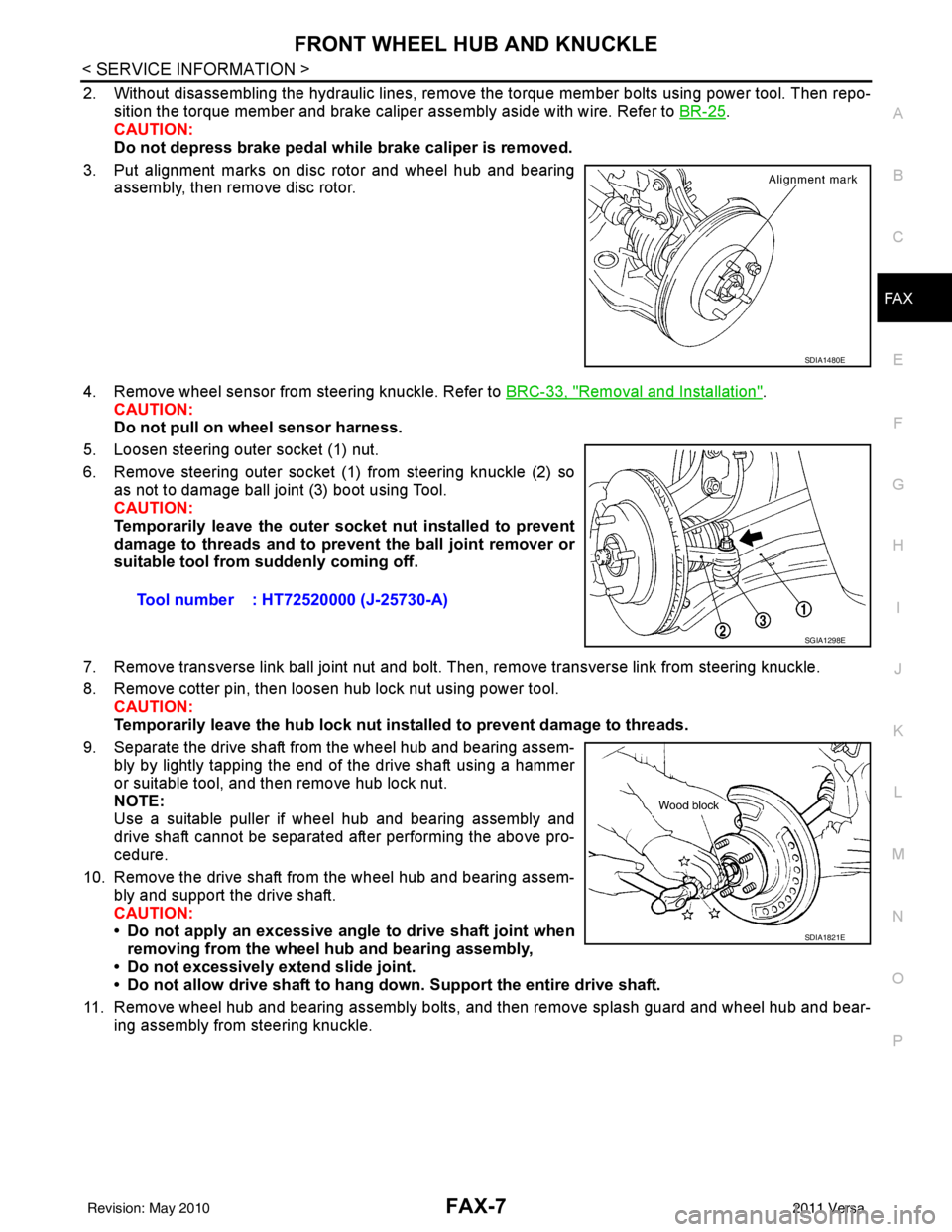
2. Without disassembling the hydraulic lines, remove the torque member bolts using power tool. Then repo- sition the torque member and brake caliper assembly aside with wire. Refer to BR-25
.
CAUTION:
Do not depress brake pedal while brake caliper is removed.
3. Put alignment marks on disc rotor and wheel hub and bearing assembly, then remove disc rotor.
4. Remove wheel sensor from steering knuckle. Refer to BRC-33, "
Removal and Installation".
CAUTION:
Do not pull on wheel sensor harness.
5. Loosen steering outer socket (1) nut.
6. Remove steering outer socket (1) from steering knuckle (2) so as not to damage ball joint (3) boot using Tool.
CAUTION:
Temporarily leave the outer socket nut installed to prevent
damage to threads and to prevent the ball joint remover or
suitable tool from suddenly coming off.
7. Remove transverse link ball joint nut and bolt. Then, remove transverse link from steering knuckle.
8. Remove cotter pin, then loosen hub lock nut using power tool. CAUTION:
Temporarily leave the hub lock nut inst alled to prevent damage to threads.
9. Separate the drive shaft from the wheel hub and bearing assem- bly by lightly tapping the end of the drive shaft using a hammer
or suitable tool, and then remove hub lock nut.
NOTE:
Use a suitable puller if wheel hub and bearing assembly and
drive shaft cannot be separated after performing the above pro-
cedure.
10. Remove the drive shaft from the wheel hub and bearing assem- bly and support the drive shaft.
CAUTION:
• Do not apply an excessive angle to drive shaft joint when
removing from the wheel hub and bearing assembly,
• Do not excessively extend slide joint.
• Do not allow drive shaft to hang do wn. Support the entire drive shaft.
11. Remove wheel hub and bearing assembly bolts, and then remove splash guard and wheel hub and bear- ing assembly from steering knuckle.
SDIA1480E
Tool number : HT72520000 (J-25730-A)
SGIA1298E
SDIA1821E
Revision: May 2010 2011 Versa
Page 2697 of 3787

FSU-12
< SERVICE INFORMATION >
COIL SPRING AND STRUT
COIL SPRING AND STRUT
Removal and InstallationINFOID:0000000005930902
REMOVAL
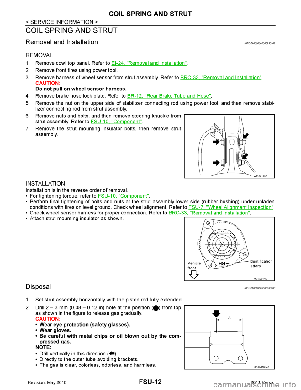
1. Remove cowl top panel. Refer to EI-24, "Removal and Installation".
2. Remove front tires using power tool.
3. Remove harness of wheel sensor from strut assembly. Refer to BRC-33, "
Removal and Installation".
CAUTION:
Do not pull on wheel sensor harness.
4. Remove brake hose lock plate. Refer to BR-12, "
Rear Brake Tube and Hose".
5. Remove the nut on the upper side of stabilizer connecting rod using power tool, and then remove stabi- lizer connecting rod from strut assembly.
6. Remove nuts and bolts, and then remove steering knuckle from strut assembly. Refer to FSU-10, "
Component".
7. Remove the strut mounting insulator bolts, then remove strut assembly.
INSTALLATION
Installation is in the reverse order of removal.
• For tightening torque, refer to FSU-10, "
Component".
• Perform final tightening of bolts and nuts at the strut assembly lower side (rubber bushing) under unladen
conditions with tires on level ground. Check wheel alignment. Refer to FSU-7, "
Wheel Alignment Inspection".
• Check wheel sensor harness for proper connection. Refer to BRC-33, "
Removal and Installation".
• Attach strut mounting insulator as shown.
DisposalINFOID:0000000005930903
1. Set strut assembly horizontally with the piston rod fully extended.
2. Drill 2 – 3 mm (0.08 – 0.12 in) hole at the position ( ) from top
as shown in the figure to release gas gradually.
CAUTION:
• Wear eye protection (safety glasses).
• Wear gloves.
• Be careful with metal chips or oil blown out by the com-pressed gas.
NOTE:
• Drill vertically in this direction ( ).
• Directly to the outer tube avoiding brackets.
• The gas is clear, colorless, odorless, and harmless.
WEIA0179E
MEIA0014E
JPEIA0160ZZ
Revision: May 2010 2011 Versa
Page 2713 of 3787

HOW TO USE THIS MANUALGI-9
< SERVICE INFORMATION >
C
DE
F
G H
I
J
K L
M B
GI
N
O P
SYMBOLS
How to Follow Trouble DiagnosisINFOID:0000000005929724
DESCRIPTION
NOTICE:
Trouble diagnoses indicate work procedures required to diagnose problems effectively. Observe the following
instructions before diagnosing.
1. Before performing trouble diagno ses, read the “Preliminary Check” , the “Symptom Chart” or the
“Work Flow”.
2. After repairs, re-check that the prob lem has been completely eliminated.
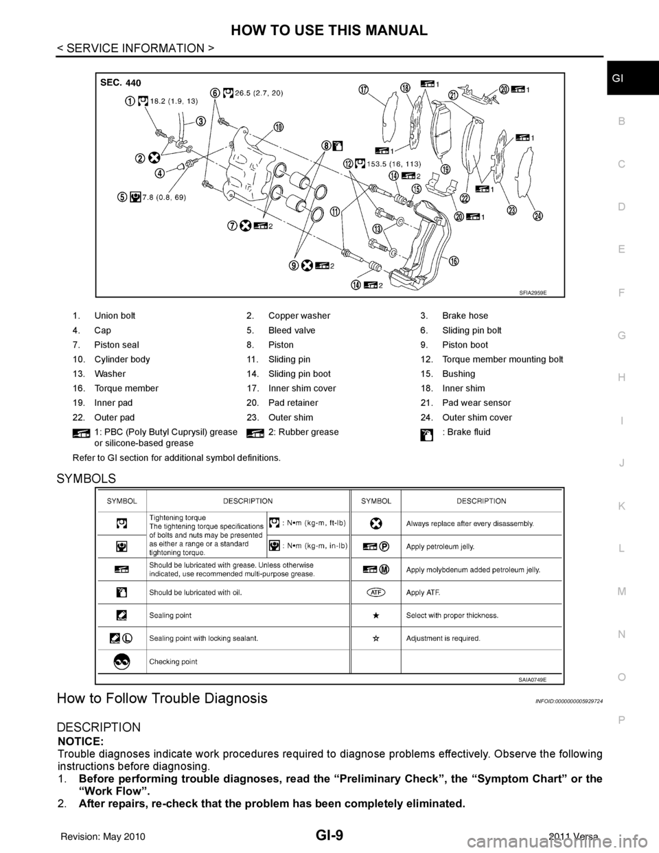
1. Union bolt 2. Copper washer3. Brake hose
4. Cap 5. Bleed valve6. Sliding pin bolt
7. Piston seal 8. Piston9. Piston boot
10. Cylinder body 11. Sliding pin12. Torque member mounting bolt
13. Washer 14. Sliding pin boot15. Bushing
16. Torque member 17. Inner shim cover18. Inner shim
19. Inner pad 20. Pad retainer21. Pad wear sensor
22. Outer pad 23. Outer shim24. Outer shim cover
1: PBC (Poly Butyl Cuprysil) grease
or silicone-based grease 2: Rubber grease
: Brake fluid
Refer to GI section for additional symbol definitions.
SFIA2959E
SAIA0749E
Revision: May 2010 2011 Versa
Page 2874 of 3787
![NISSAN TIIDA 2011 Service Repair Manual LAN-28
< SERVICE INFORMATION >[CAN]
CAN COMMUNICATION SYSTEM
*1: A/T models
*2: CVT models
*3: Models with VDC
*4: Models for Canada
*5: Models for USA
*6: Models without ABS
NOTE:
CAN data of the air NISSAN TIIDA 2011 Service Repair Manual LAN-28
< SERVICE INFORMATION >[CAN]
CAN COMMUNICATION SYSTEM
*1: A/T models
*2: CVT models
*3: Models with VDC
*4: Models for Canada
*5: Models for USA
*6: Models without ABS
NOTE:
CAN data of the air](/manual-img/5/57396/w960_57396-2873.png)
LAN-28
< SERVICE INFORMATION >[CAN]
CAN COMMUNICATION SYSTEM
*1: A/T models
*2: CVT models
*3: Models with VDC
*4: Models for Canada
*5: Models for USA
*6: Models without ABS
NOTE:
CAN data of the air bag diagnosis sensor unit is not used by usual service work, thus it is omitted.
KEY warning lamp signal
T R
LOCK warning lamp signal T R
Panic alarm request signal RT
Fuel level sensor signal RT
Overdrive control switch signal TR R
Parking brake switch signal
*3TR
Stop lamp switch signal T R R
Vehicle speed signal RRRR T
RRR T R
R
*6T*6
Steering angle sensor signal*3TR
ABS warning lamp signal RT
Brake warning lamp signal RT
SLIP indicator lamp signal
*3RT
VDC OFF indicator lamp signal
*3RT
VDC warning lamp signal
*3RT
A/T check indicator signal RT
A/T self-diagnosis signal R T
Input speed signal R T
OD OFF indicator signal RT
Output shaft revolution signal R T T
Shift position indicator signal R
R
*3TT
CVT self-diagnosis signal R T
Input shaft revolution signal R T
OD OFF indicator signal RT
Front wiper stop position signal R T
High beam status signal R T
Low beam status signal R T
Oil pressure switch signal R RR T
Rear window defogger control signal R T
Signal name/Connecting unit
ECM
BCM
EPS
I-KEY M&A
STRG ABS
TCM
*1
TCM
*2
IPDM-E
Revision: May 2010 2011 Versa
Page 3461 of 3787

HARNESSPG-41
< SERVICE INFORMATION >
C
DE
F
G H
I
J
L
M A
B
PG
N
O P
C2 M6 W/4 : Steering lock solenoid D2 M43 W/20 : Audio unit
B3 M7 W/16 : Door mirror re mote control switch D2 M44 W/16 : Audio unit
A3 M8 W/16 : To D2 D2 M45 W/12 : Audio unit
A3 M9 W/16 : To D1 A1 M46 BR/2 : Front tweeter LH
E2 M10 GR/2 : Instrument panel antenna G1 M47 BR/2 : Front tweeter RH
G3 M11 W/4 : To B106 B2 M48 L/4 : Heated mirror relay
G4 M12 W/16 : To B101 D3 M49 W/24 : iPod ® adapter
G3 M13 W/24 : To B102 E1 M50 GR/16 : iPod ® side
G3 M14 W/24 : To B120 E2 M52 W/40 : Intelligent key unit
B4 M15 W/16 : To B23 B2 M53 W/16 : EPS control unit
B4 M16 W/24 : To B24 B3 M54 B/2 : EPS control unit
D5 M17 B/1 : Parking brake switch D2 M55 W/4 : Hazard switch
F2 M18 W/40 : BCM (body control module) B2 M57 — : Body ground
F2 M19 W/15 : BCM (body control module) C1 M60 L/2 : EPS control unit
F3 M20 B/15 : BCM (body control module) F1 M61 — : Body ground
C2 M21 W/4 : NATS antenna amp. E2 M62 W/2 : Front blower motor
B3 M22 W/16 : Data link connector C1 M63 W/4 : Torque sensor
E3 M23 W/4 : Remote keyless entry receiver C3 M64 W/8 : Steering angle sensor
C1 M24 W/40 : Combination meter A2 M69 SMJ : To E7
C3 M25 /2 : Diode-1 D2 M70 W/24 : AV control unit
B2 M26 W/6 : Ignition switch D2 M71 W/9 : AV control unit
C2 M27 GR/6 : Key switch and key lock solenoid D1 M72 B/5 : USB interface and aux jack
C2 M28 W/16 : Combination switch B2 M73 GR/6 : Key switch and ignition knob switch
C3 M29 Y/6 : Combination switch G3 M74 W/12 : To D102
C3 M30 GR/8 : Combination switch G3 M75 W/12 : To D101
E3 M32 W/4 : To M150 E1 M76 B/4 : USB interface and aux jack
D2 M33 B/15 : Front air control F2 M77 Y/4 : Front passenger air bag module
B3 M34 GR/6 : VDC OFF switch A2 M78 B/2 : To E11
D4 M35 Y/28 : Air bag diagnosis sensor unit B1 M79 — : Body ground
C3 M36 W/3 : Front passenger air bag OFF indicator D3 M150 W/4 : To M32
D4 M38 W/6 : A/T shift selector (with A/T) C3 M151 W/4 : Front blower motor resistor
D4 M38 W/6 : CVT shift selector (without intelligent
key)
Revision: May 2010
2011 Versa
Page 3463 of 3787

HARNESSPG-43
< SERVICE INFORMATION >
C
DE
F
G H
I
J
L
M A
B
PG
N
O P
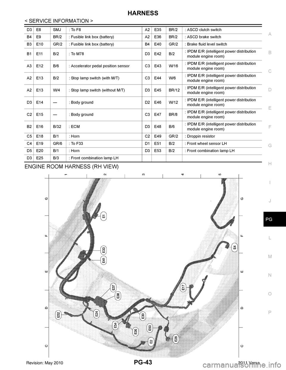
ENGINE ROOM HARNESS (RH VIEW)
D3 E8 SMJ : To F8 A2 E35 BR/2 : ASCD clutch switch
B4 E9 BR/2 : Fusible link box (battery) A2 E36 BR/2 : ASCD brake switch
B3 E10 GR/2 : Fusible link box (battery) B4 E40 GR/2 : Brake fluid level switch
B1 E11 B/2 : To M78 D3 E42 B/2: IPDM E/R (intelligent power distribution
module engine room)
A3 E12 B/6 : Accelerator pedal position sensor C3 E43 W/16 : IPDM E/R (intelligent power distribution
module engine room)
A2 E13 B/2 : Stop lamp switch (with M/T) C3 E44 W/6: IPDM E/R (intelligent power distribution
module engine room)
A2 E13 W/4 : Stop lamp switch (without M/T) D3 E45 BR/12: IPDM E/R (intelligent power distribution
module engine room)
D3 E14 — : Body ground D2 E46 W/12: IPDM E/R (intelligent power distribution
module engine room)
C2 E15 — : Body ground C3 E47 BR/8: IPDM E/R (intelligent power distribution
module engine room)
B2 E16 B/32 : ECM D3 E48 B/6: IPDM E/R (intelligent power distribution
module engine room)
C5 E18 B/1 : Horn C2 E49 GR/2 : Droppin resistor
C4 E19 GR/6 : To F33 D1 E51 B/2 : Front wheel sensor LH
D5 E20 B/1 : Horn D3 E53 B/2 : Front combination lamp LH
D3 E25 B/3 : Front combination lamp LH
Revision: May 2010 2011 Versa
Page 3478 of 3787

PG-58
< SERVICE INFORMATION >
HARNESS
Wiring Diagram Codes (Cell Codes)
INFOID:0000000005928356
Use the chart below to find out what each wiring diagram code stands for.
Refer to the wiring diagram code in the alphabetical index to find the location (page number) of each wiring
diagram.
D4 D406 W/2 : Back door request switch C2 D413 B/1 : Rear window defogger (-)
E2 D407 W/2 : High mounted stop lamp
Code Section Wiring Diagram Name
ABS BRC Anti-lock Brake System
A/C,M MTC Manual Air Conditioner
APPS1 EC Accelerator Pedal Position Sensor
A/F EC Air Fuel Ratio Sensor 1
A/FH EC Air Fuel Ratio Sensor 1 Heater
APPS2 EC Accelerator Pedal Position Sensor
APPS3 EC Accelerator Pedal Position Sensor
ASC/BS EC ASCD Brake Switch
ASC/SW EC ASCD Steering Switch
ASCBOF EC ASCD Brake Switch
ASCIND EC ASCD Indicator
AT/IND DI A/T Indicator Lamp
AUDIO AV Audio
BACK/L LT Back-up Lamp
BA/FTS AT A/T Fluid Temperature Sensor and TCM Power Supply
B/DOOR BL Back Door Opener
BRK/SW EC Brake Switch
CAN AT CAN Communication Line
CAN CVT CAN Communication Line
CAN EC CAN Communication Line
CAN LAN CAN System
CHARGE SC Charging System
CHIME DI Warning Chime
COOL/F EC Cooling Fan Control
COMBSW LT Combination Switch
COMM AV Audio Visual Communication System
CVTIND DI CVT Indicator Lamp
D/LOCK BL Power Door Lock
DEF GW Rear Window Defogger
DTRL LT Headlamp - With Daytime Light System
ECTS EC Engine Coolant Temperature Sensor
ENGSS AT Engine Speed Signal
EPS STC Electronic Controlled Power Steering
ETC1 EC Electric Throttle Control Function
ETC2 EC Throttle Control Motor Relay
ETC3 EC Throttle Control Motor
F/FOG LT Front Fog Lamp
F/PUMP EC Fuel Pump
FTS AT A/T Fluid Temperature Sensor
FTS CVT CVT Fluid Temperature Sensor Circuit
FTTS EC Fuel Tank Temperature Sensor
FUEL EC Fuel Ignition System Function
HEATER MTC Heater System
Revision: May 2010 2011 Versa
Page 3522 of 3787

WHEEL HUBRAX-7
< SERVICE INFORMATION >
CEF
G H
I
J
K L
M A
B
RAX
N
O P
Do not pull on wheel sensor harness.
3. Remove the brake drum only. Refer to BR-36, "
Removal and Installation of Drum Brake Assembly".
4. Remove wheel hub and bearing assembly bolts, and then remove wheel hub and bearing assembly from vehicle.
5. Suspend back plate with suitable wire, or if necessary, remove back plate using the following procedure. 1. Remove parking brake rear cable from back plate. Refer to PB-6, "
Removal and Installation".
2. Separate brake tube from wheel cylinder. Refer to BR-12, "
Rear Brake Tube and Hose".
INSPECTION AFTER REMOVAL
Check for any deformity, cracks, or other damage on the wheel hub assembly, replace if necessary.
CAUTION:
The wheel hub assembly does not requ ire maintenance. If any of the following symptoms are noted,
replace the wheel hub assembly.
• Growling noise is emitted from the wheel hub bearing during operation.
• Wheel hub bearing drags or turns roughly.
INSTALLATION
Installation is in the reverse order of removal.
Revision: May 2010 2011 Versa