Page 853 of 3787
BR-6
< SERVICE INFORMATION >
BRAKE PEDAL
BRAKE PEDAL
Inspection and AdjustmentINFOID:0000000005928391
INSPECTION
1. Check brake pedal free height (H) from dash panel top surfaceusing Tool.
2. Check clearance between pedal stopper and threaded end of stop lamp switch (C
1) and ASCD cancel switch (C2), if equipped.
•
ADJUSTMENT
Tool number : — (J-46532)
AWFIA0557ZZ
Brake pedal free height (H) (from dash panel top surface) : Refer to BR-41, "Brake Pedal".
Brake pedal full stroke (S) : Refer to BR-41, "
Brake Pedal".
Clearance between pedal stopper and threaded end of stop
lamp switch (C
1) and ASCD cancel switch (C2), if equipped. : Refer to
BR-41, "Brake Pedal".
Revision: May 2010 2011 Versa
Page 855 of 3787

BR-8
< SERVICE INFORMATION >
BRAKE PEDAL
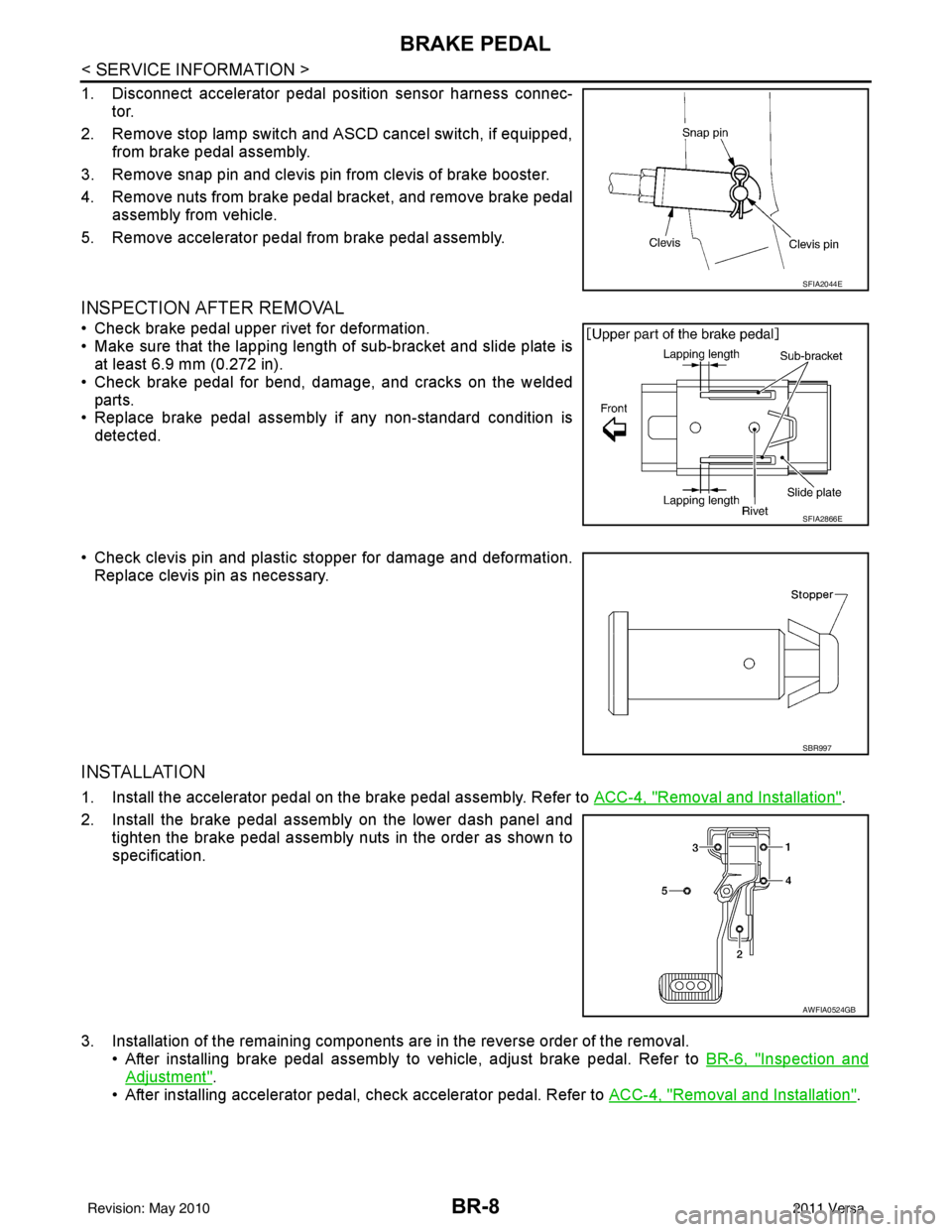
1. Disconnect accelerator pedal position sensor harness connec-tor.
2. Remove stop lamp switch and ASCD cancel switch, if equipped, from brake pedal assembly.
3. Remove snap pin and clevis pin from clevis of brake booster.
4. Remove nuts from brake pedal bracket, and remove brake pedal assembly from vehicle.
5. Remove accelerator pedal from brake pedal assembly.
INSPECTION AFTER REMOVAL
• Check brake pedal upper rivet for deformation.
• Make sure that the lapping length of sub-bracket and slide plate is at least 6.9 mm (0.272 in).
• Check brake pedal for bend, damage, and cracks on the welded parts.
• Replace brake pedal assembly if any non-standard condition is
detected.
• Check clevis pin and plastic stopper for damage and deformation. Replace clevis pin as necessary.
INSTALLATION
1. Install the accelerator pedal on the brake pedal assembly. Refer to ACC-4, "Removal and Installation".
2. Install the brake pedal assembly on the lower dash panel and tighten the brake pedal assembly nuts in the order as shown to
specification.
3. Installation of the remaining components are in the reverse order of the removal. • After installing brake pedal assembly to vehicle, adjust brake pedal. Refer to BR-6, "
Inspection and
Adjustment".
• After installing accelerator pedal, check accelerator pedal. Refer to ACC-4, "
Removal and Installation".
SFIA2044E
SFIA2866E
SBR997
AWFIA0524GB
Revision: May 2010 2011 Versa
Page 867 of 3787
BR-20
< SERVICE INFORMATION >
BRAKE BOOSTER
BRAKE BOOSTER
On Board InspectionINFOID:0000000005928405
OPERATING CHECK
• With the engine stopped, change the vacuum to the atmospheric pressure by depressing brake pedal sev-
eral times at intervals of 5 seconds.
• Then with brake pedal fully depressed, start engine and when the vacuum pressure reaches the standard, make sure that the clear-
ance between brake pedal and floor panel decreases.
AIRTIGHT CHECK
• Run engine at idle for approximately 1 minute, and stop it afterapplying vacuum to booster. Depress brake pedal normally to
change the vacuum to the atmospheric pressure. Make sure that
distance between brake pedal and floor panel gradually increases.
• Depress the brake pedal while engine is running, then stop engine with brake pedal depressed. The pedal
stroke should not change after holding pedal down for 30 seconds.
WFIA0520E
WFIA0521E
Revision: May 2010 2011 Versa
Page 868 of 3787
BRAKE BOOSTERBR-21
< SERVICE INFORMATION >
C
DE
G H
I
J
K L
M A
B
BR
N
O P
Removal and InstallationINFOID:0000000005928406
REMOVAL
CAUTION:
• Be careful not to splash brake fluid on painted areas such as body. It may cause paint damage. If brake fluid is splashed on painte d surfaces of body, wipe them with cloth immediately and then wash
it away with water.
• Be careful not to deform or bend brake tub es while removing and installing brake booster.
• Replace clevis pin if it is damaged.
• Be careful not to damage brake booster stud bolt thr eads. If brake booster is tilted or inclined during
installation, dash panel may damage the threads.
1. Remove vacuum hose from brake booster.
2. Remove master cylinder assembly. Refer to BR-15, "
Removal and Installation".
3. Remove the instrument lower finisher. Refer to IP-11, "
Component Parts".
1. Reservoir tank2. Master cylinder 3. Brake booster
4. Clevis 5. Spacer 6. Gasket
Up
AWFIA0530GB
Revision: May 2010 2011 Versa
Page 869 of 3787

BR-22
< SERVICE INFORMATION >
BRAKE BOOSTER
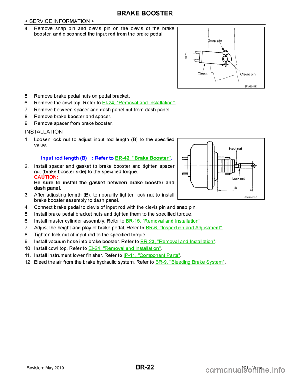
4. Remove snap pin and clevis pin on the clevis of the brakebooster, and disconnect the input rod from the brake pedal.
5. Remove brake pedal nuts on pedal bracket.
6. Remove the cowl top. Refer to EI-24, "
Removal and Installation".
7. Remove between spacer and dash panel nut from dash panel.
8. Remove brake booster and spacer.
9. Remove spacer from brake booster.
INSTALLATION
1. Loosen lock nut to adjust input rod length (B) to the specified value.
2. Install spacer and gasket to brake booster and tighten spacer nut (brake booster side) to the specified torque.
CAUTION:
Be sure to install the gasket between brake booster and
dash panel.
3. After adjusting length (B), temporarily tighten lock nut to install brake booster assembly to dash panel.
4. Connect brake pedal to clevis of input rod with the clevis pin and snap pin.
5. Install brake pedal bracket nuts and tighten them to the specified torque.
6. Install master cylinder assembly. Refer to BR-15, "
Removal and Installation".
7. Adjust the height and play of brake pedal. Refer to BR-6, "
Inspection and Adjustment".
8. Tighten lock nut of input rod to the specified torque.
9. Install vacuum hose into brake booster. Refer to BR-23, "
Removal and Installation".
10. Install cowl top. Refer to EI-24, "
Removal and Installation".
11. Install instrument lower finisher. Refer to IP-11, "
Component Parts".
12. Bleed the air from the brake hydraulic system. Refer to BR-9, "
Bleeding Brake System".
SFIA2044E
Input rod length (B) : Refer to BR-42, "Brake Booster".
SGIA0060E
Revision: May 2010 2011 Versa
Page 888 of 3787
SERVICE DATA AND SPECIFICATIONS (SDS)BR-41
< SERVICE INFORMATION >
C
DE
G H
I
J
K L
M A
B
BR
N
O P
Brake PedalINFOID:0000000005928421
Unit: mm (in)
Check ValveINFOID:0000000005928422
Brake pedal free height (H) (from dash panel top surface) A/T, CVT model 172.4 - 182.4 (6.79 - 7.18)
M/T model 162.3 - 172.3 (6.39 - 6.78)
Brake pedal full stroke (S) 133 (5.24)
Clearance between the pedal stopper and threaded end of stop lamp switch (C
1) and ASCD cancel
switch (C
2), if equipped 0.74 - 1.96 (0.0291 - 0.0772)
AWFIA0557ZZ
When connected to booster side (1)
Within 1.3 kPa (10 mmHg, 0.39 inHg) of vacuum for 15 seconds
[at vacuum of – 66.7 kPa (– 500 mmHg, – 19.69 inHg]
When connected to engine side (2) No vacuum will be applied
SFIA0210E
Revision: May 2010 2011 Versa
Page 1082 of 3787
![NISSAN TIIDA 2011 Service Repair Manual ON BOARD DIAGNOSTIC (OBD) SYSTEMCVT-27
< SERVICE INFORMATION > [RE0F08B]
D
E
F
G H
I
J
K L
M A
B
CVT
N
O P
ON BOARD DIAGNOSTIC (OBD) SYSTEM
IntroductionINFOID:0000000005928743
The CVT system has two s NISSAN TIIDA 2011 Service Repair Manual ON BOARD DIAGNOSTIC (OBD) SYSTEMCVT-27
< SERVICE INFORMATION > [RE0F08B]
D
E
F
G H
I
J
K L
M A
B
CVT
N
O P
ON BOARD DIAGNOSTIC (OBD) SYSTEM
IntroductionINFOID:0000000005928743
The CVT system has two s](/manual-img/5/57396/w960_57396-1081.png)
ON BOARD DIAGNOSTIC (OBD) SYSTEMCVT-27
< SERVICE INFORMATION > [RE0F08B]
D
E
F
G H
I
J
K L
M A
B
CVT
N
O P
ON BOARD DIAGNOSTIC (OBD) SYSTEM
IntroductionINFOID:0000000005928743
The CVT system has two self-diagnostic systems.
The first is the emission-related on board diagnostic syst em (OBD-II) performed by the TCM in combination
with the ECM. The malfunction is indicated by the MI L (malfunction indicator lamp) and is stored as a DTC in
the ECM memory, and the TCM memory.
The second is the TCM original self-diagnosis perform ed by the TCM. The malfunction is stored in the TCM
memory. The detected items are overlapped with OBD-II self-diagnostic items. For detail, refer to CVT-48,
"CONSULT-III Function (TRANSMISSION)".
OBD-II Function for CVT SystemINFOID:0000000005928744
The ECM provides emission-related on board diagnostic (OBD-II) functions for the CVT system. One function
is to receive a signal from the TCM used with OBD-relat ed parts of the CVT system. The signal is sent to the
ECM when a malfunction occurs in the corresponding OBD-re lated part. The other function is to indicate a
diagnostic result by means of the MIL (malfunction indica tor lamp) on the instrument panel. Sensors, switches
and solenoid valves are used as sensing elements.
The MIL automatically illuminates in One or Two Trip Detection Logic when a malfunction is sensed in relation
to CVT system parts.
One or Two Trip Detection Logic of OBD-IIINFOID:0000000005928745
ONE TRIP DETECTION LOGIC
If a malfunction is sensed during the first test drive, the MIL will illuminate and the malfunction will be stored in
the ECM memory as a DTC. The TCM is not provided with such a memory function.
TWO TRIP DETECTION LOGIC
When a malfunction is sensed during the first test drive, it is stored in the ECM memory as a 1st trip DTC
(diagnostic trouble code) or 1st trip freeze frame data. At this point, the MIL will not illuminate. — 1st trip
If the same malfunction as that experienced during the fi rst test drive is sensed during the second test drive,
the MIL will illuminate. — 2nd trip
The “trip” in the “One or Two Trip Detection Logic” m eans a driving mode in which self-diagnosis is performed
during vehicle operation.
OBD-II Diagnostic Trouble Code (DTC)INFOID:0000000005928746
HOW TO READ DTC AND 1ST TRIP DTC
DTC and 1st trip DTC can be read by the following methods.
( with CONSULT-III or GST) CONSULT-III or GST (Generic Scan Tool) Examples: P0705, P0720 etc.
These DTC are prescribed by SAE J2012.
(CONSULT-III also displays the malfunctioning component or system.)
• 1st trip DTC No. is the same as DTC No.
• Output of the diagnostic trouble code indicates that the indicated circuit has a malfunction. How-
ever, in case of the Mode II and GST, they do not indicate whether the malfunction is still occurring or
occurred in the past and returned to normal.
CONSULT-III can identify them as shown below, therefore, CONS ULT-III (if available) is recom-
mended.
DTC or 1st trip DTC of a malfunction is displayed in SELF-DIAGNOSTIC RESULTS mode for “ENGINE” with
CONSULT-III. Time data indicates how many times the vehicle was driven after the last detection of a DTC.
If the DTC is being detected curr ently, the time data will be “0”.
If a 1st trip DTC is stored in the ECM, the time data will be “1t”.
Freeze Frame Data and 1st Trip Freeze Frame Data
Revision: May 2010 2011 Versa
Page 1084 of 3787
ON BOARD DIAGNOSTIC (OBD) SYSTEMCVT-29
< SERVICE INFORMATION > [RE0F08B]
D
E
F
G H
I
J
K L
M A
B
CVT
N
O P
The MIL is located on the instrument panel.
1. The MIL will light up when the ignition switch is turned ON with- out the engine running. This is a bulb check.
• If the MIL does not light up, refer to DI-21, "
Schematic", or see
EC-1033, "
Wiring Diagram".
2. When the engine is start ed, the MIL should go off.
If the MIL remains on, the on board diagnostic system has
detected an engine system malfunction.
SEF217U
Revision: May 2010 2011 Versa